Need some help with a wiring diagram.
#1
 01-18-2016, 06:15 PM


So, I kinda messed up the job of changing out my CPS. I accidentally broke the harness end plug. I've got Abran sending me a new one off one of his parts trucks, but I figure the easiest way to remedy the situation is to just run new wire for the plug since I can't get my hands back where I need to to crimp into the wire that's already there, so I have been looking at the wiring diagrams for our trucks. You can find the whole thing here, but I've included the page that has the diagram showing the wires from the ECU to the crank position sensor.
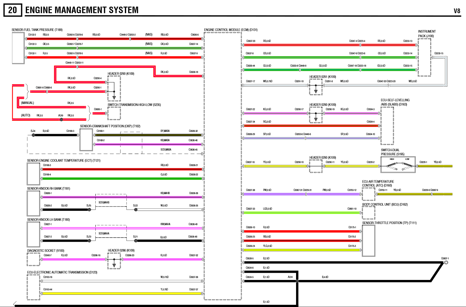
Now, the black/yellow and the purple/black wire I understand perfectly. The part I need help with is the black that connects to the dotted lines. I've marked them here.
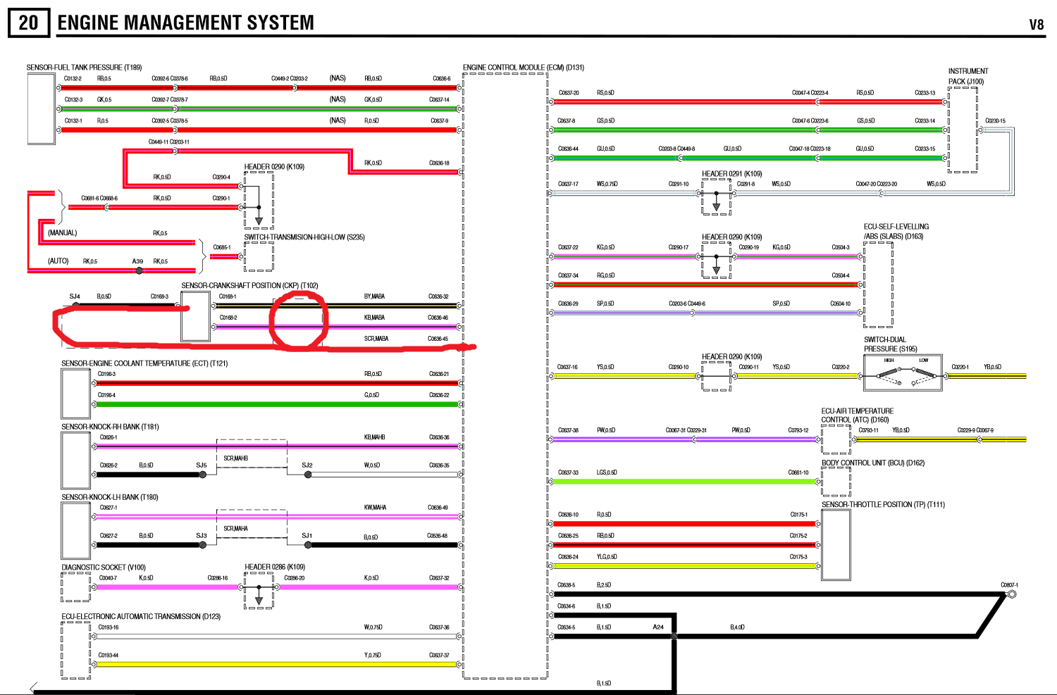
So, since I haven't really been able to see it yet, are there three wires in the back of the plug? I'm assuming that's the case. If that is the case, then where does the black one run to? Is that just a ground that I can connect anywhere or do I need to run it back to the ECU? Also, why does the diagram show it looped around the other two wires?
Thanks guys!
Now, the black/yellow and the purple/black wire I understand perfectly. The part I need help with is the black that connects to the dotted lines. I've marked them here.
So, since I haven't really been able to see it yet, are there three wires in the back of the plug? I'm assuming that's the case. If that is the case, then where does the black one run to? Is that just a ground that I can connect anywhere or do I need to run it back to the ECU? Also, why does the diagram show it looped around the other two wires?
Thanks guys!
Last edited by Alex_M; 01-22-2016 at 07:36 PM.
#2
01-19-2016, 12:56 AM


Sound as if you're trying to do a temp repair on your harness or the plug on your spare CKP?
Appears circuit shielded on harness side to ECM. Black wire and harness shield are supposed to be joined/spliced together. Shields do normally go to ground and cable shields usually are grounded to component gnd.
Consequences of not having proper shielding circuit will not prevent the CKP signal reaching the the ECM but could be less stable than desired.
That said you may be fine running CKP wire to a gnd but my only pro experience has been fixin' big ol' jetliners.
......
Appears circuit shielded on harness side to ECM. Black wire and harness shield are supposed to be joined/spliced together. Shields do normally go to ground and cable shields usually are grounded to component gnd.
Consequences of not having proper shielding circuit will not prevent the CKP signal reaching the the ECM but could be less stable than desired.
That said you may be fine running CKP wire to a gnd but my only pro experience has been fixin' big ol' jetliners.
Last edited by number9; 01-19-2016 at 12:57 AM. Reason: space
#3
01-19-2016, 08:02 AM
I was actually hoping this would be a permanent repair on the harness. So should I run the black to ground and then get some electromagnetic shielding mesh to wrap around the other two? Again, really hoping for a permanent solution here so don't have to pull the head to splice this harness plug in.
#4
01-19-2016, 06:13 PM
I was actually hoping this would be a permanent repair on the harness. So should I run the black to ground and then get some electromagnetic shielding mesh to wrap around the other two? Again, really hoping for a permanent solution here so don't have to pull the head to splice this harness plug in.
easiest way to remedy the situation is to just run new wire for the plug
If that doesn't help can you sketch what you want to do in simple wiring diagram form? Without seeing what you have it's difficult knowing what you want to do. Shielding probably not that critical and may work without.
......
#5
01-19-2016, 08:07 PM
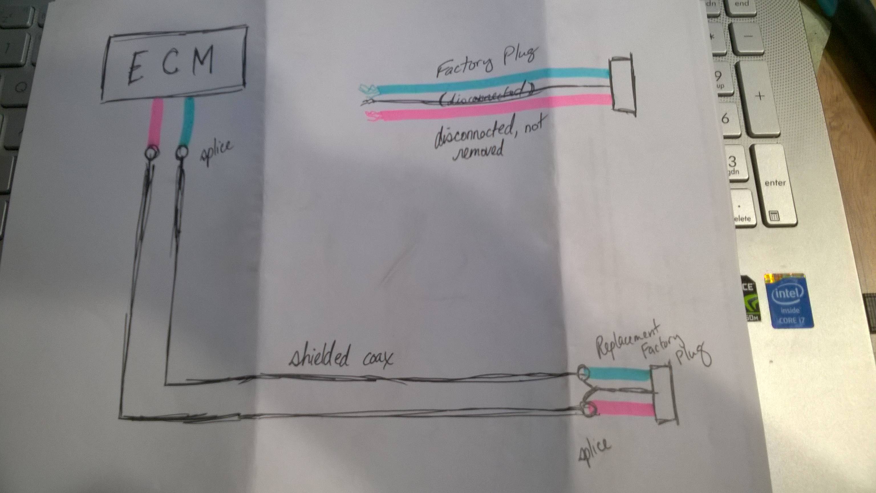
Yea, I was planning on running new wire the entire way. Yea, there will be a factory style connector that the sensor will be able to plug into. Abran is sending me one off of a truck he's taking apart. I can solder it all no problem. Since the wire is shielded, I may actually just run a couple strands of coaxial and solder the shielding into the wire on the plug Abran sent today.
Here's the little diagram I drew up.
Here's the little diagram I drew up.
#6
01-19-2016, 08:28 PM
What's the shielding look like on ECM side? Is the existing harness a shielded twisted pair or just straight individuals? Haven't had to access mine yet to see what they used. The shields should be connected together at your splices on that end too. Guess some of my questions will be answered soon since as a new CKP was ordered and heading my way. I will be extra careful with my connectors.
Looks like you have everything under control with your diagram and plans.
......
Looks like you have everything under control with your diagram and plans.
......
Last edited by number9; 01-19-2016 at 08:38 PM.
#9
01-22-2016, 03:04 PM
So, I've been looking at a TD5 wiring diagram. Luckily I have yet to start cutting into my wiring harness, so I haven't caused any issues yet, but I am having trouble finding a V8 wiring diagram. The RAVE has some info on which pins are which on which plugs, but there are no wire colors listed. Anyone have any ideas where I could find a diagram for a V8?

