
Rocker switch placement???

#22
 11-24-2015, 02:14 PM

#23
11-24-2015, 03:52 PM


#25
12-12-2015, 11:43 PM

here is my solution.
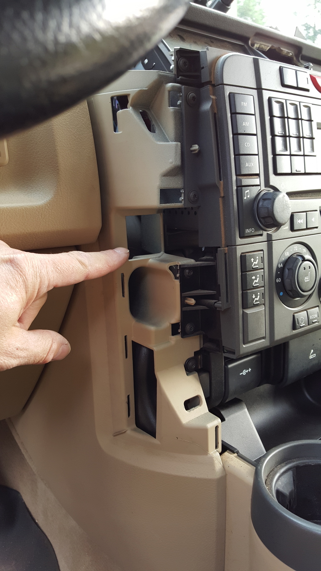
I ran jacketed two conductor (the flat looking grey wire in the first picture) from the engine bay through the A-pillar and out behind the trim piece beside the dash. From there it heads to the panel below the steering wheel. There is a good sized empty spot behind the panel that makes running the wires quite easy. I removed the panel and used a step drill (from both sides) to drill the mounting holes. The wires are spliced with the goofy blue splice things because it is the simple way to run power and ground for the relay trigger wire and to power the LED indicator on the switch. The relay (and consequently the accessory) is powered with larger gauge wire in a fused direct feed from the battery or a fused ignition controlled feed.
I have made two runs of the jacketed two wire through the driver's A-piilar, one for relay trigger power and ground and one for the trigger wire for my LED light bar. I have also made a run of three wires through the passenger A-pillar for my two way road radio. (power, ground, and antenna). With the hood closed and the exterior and interior trim replaced, no one can tell the where the wires are run.

#27
12-13-2015, 11:10 PM
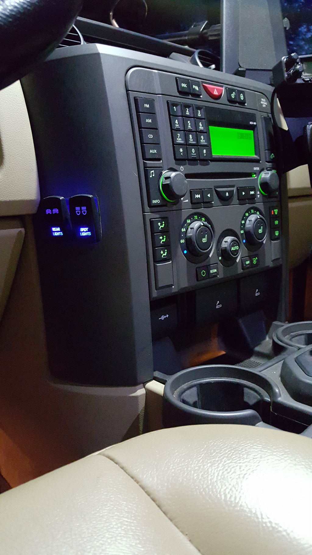
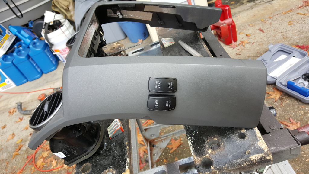
I stole an idea from somebody else (can't find the pics) and put two rockers into the side of the radio bezel. There's just enough open space behind to fit them here, so measure carefully before you cut. They are also high enough I don't hit them with my knee, but if you were extremely long of leg you might bump them if you aren't careful. At 5' 10", I can't accidentally bump them.

#28
12-15-2015, 10:35 PM
upload troubles keep me from posting a reply. I wanted to attach a couple pics, but there seems to be an issue.
Anyway BBYER, yes, the wires are run in the same fashion on both sides. A closer read of my previous post and you can see I have written that I used one side for the two way radio and the other side for LED light bar switches.
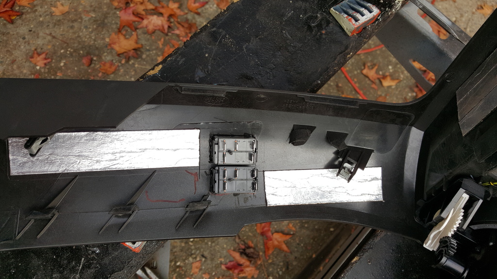
the catch is that one has to remove the lower foam block (or part of it anyway) on the back side of the trim piece to make room for the wires. also, it's a pretty good idea to buy a stock of the body clips that hold the trim on. they are brittle.
Anyway BBYER, yes, the wires are run in the same fashion on both sides. A closer read of my previous post and you can see I have written that I used one side for the two way radio and the other side for LED light bar switches.
the catch is that one has to remove the lower foam block (or part of it anyway) on the back side of the trim piece to make room for the wires. also, it's a pretty good idea to buy a stock of the body clips that hold the trim on. they are brittle.
The following users liked this post:
bbyer (12-15-2015)
#29
12-18-2015, 10:57 AM
I stole an idea from somebody else (can't find the pics) and put two rockers into the side of the radio bezel. There's just enough open space behind to fit them here, so measure carefully before you cut. They are also high enough I don't hit them with my knee, but if you were extremely long of leg you might bump them if you aren't careful. At 5' 10", I can't accidentally bump them.

That's perfect. Exactly where I was thinking
#30
12-18-2015, 11:19 AM
Here area couple pics of the installation. Basically there's an empty pocket behind that area you can fit the switch wiring into but it's pretty tight so measure closely. I think you could get a 3rd switch below these but not sure, and you'd probably bump it with your knee if you did put one lower.


The following users liked this post:
bbyer (12-18-2015)