Rebuilding my v8
#1
 06-08-2016, 01:18 PM


Soo... I wrote this all out, was almost finished when my computer locked up. Second times always better right?
I don't typically document things and I hadn't planned on doing it for this build but thought that I should for a couple reasons.
1.) It might help someone out in the future.
1a.) It might convince someone to try to do the work to fix their Land Rover themselves, thereby keeping another Rover out of the junk yard.
2.) I can get free comments and critique on things I might be doing wrong.
I see plenty of cheap Discovery's around with nothing but a few engine problems, hopefully this helps the community.
I don't have any fancy tools, most of my stuff was bought from Lowes or Harbor Freight. I don't have a whole lot of money, so this will be on a budget. I'm pretty decent with a wrench and it's not my first time inside an engine, but for anyone considering this, these are probably the easiest style of engine to work on. All that being said, if I can do this... so can you.
Some preface here though, my Land Rover was running great. Nothing wrong with it... or so the idiot lights said. The only sign that I had an issue was occasionally a lifter would stick and cause quite a bit of noise. In the harsh cold of Alabama winter, sometimes the oil pressure light would take 10 seconds or so to go away. I knew this was not normal and it worried me a little bit. This engine when warm, and in warm weather ran great.
I had previously installed a cheap set of gauges. Coolant Temp, Oil Pressure and Oil Temperature. The oil temperature gauge really isn't needed, but the first two are pretty much mandatory. If you don't have these installed, stop what you are doing and order them. Now. They are cheap, easy to install and tell you way more than the dummy stuff the Discovery comes with.
My engine never ran hot, around 185-190. Once while off-roading, I noticed the temp climb up to the 202-ish range, but immediately went down once the truck was moving. My oil pressure on the other hand, was an issue. No matter what viscosity of oil or temperature, the oil pressure never went over 22-25psi. Hot idle pressure was as low as 5-8psi, but I can't be for certain as cheap gauges often are inaccurate at their extremes. Either way, the oil pressure was quite low and the dummy gauge didn't turn on. Scary.
I guess my motor is probably quite representative of the majority now. High mileage, questionable past and in need of some TLC.
The Land Rover Workshop Manual is invaluable but sometimes not the easiest to follow, especially if you haven't done this before. A very valuable resource is the Land Rover Toolbox Video's on YouTube. Although most of his video's are featuring the TDI engine and Defenders, he does have some helpful videos for learning techniques.
I'll be completely rebuilding this motor with as much detail as you want. If you want more detail on a specific thing, just let me know and I'll do my best to document it for you. If you see me doing something wrong, correct me! If you know a better way to do something, let me know!
I didn't intend to document this, but I started to... so the next few posts will be catching you up to where I am currently.
The following 2 users liked this post by xathor:
Gimebakmybulits (06-10-2016),
grenade (05-24-2018)
#2
06-08-2016, 01:40 PM
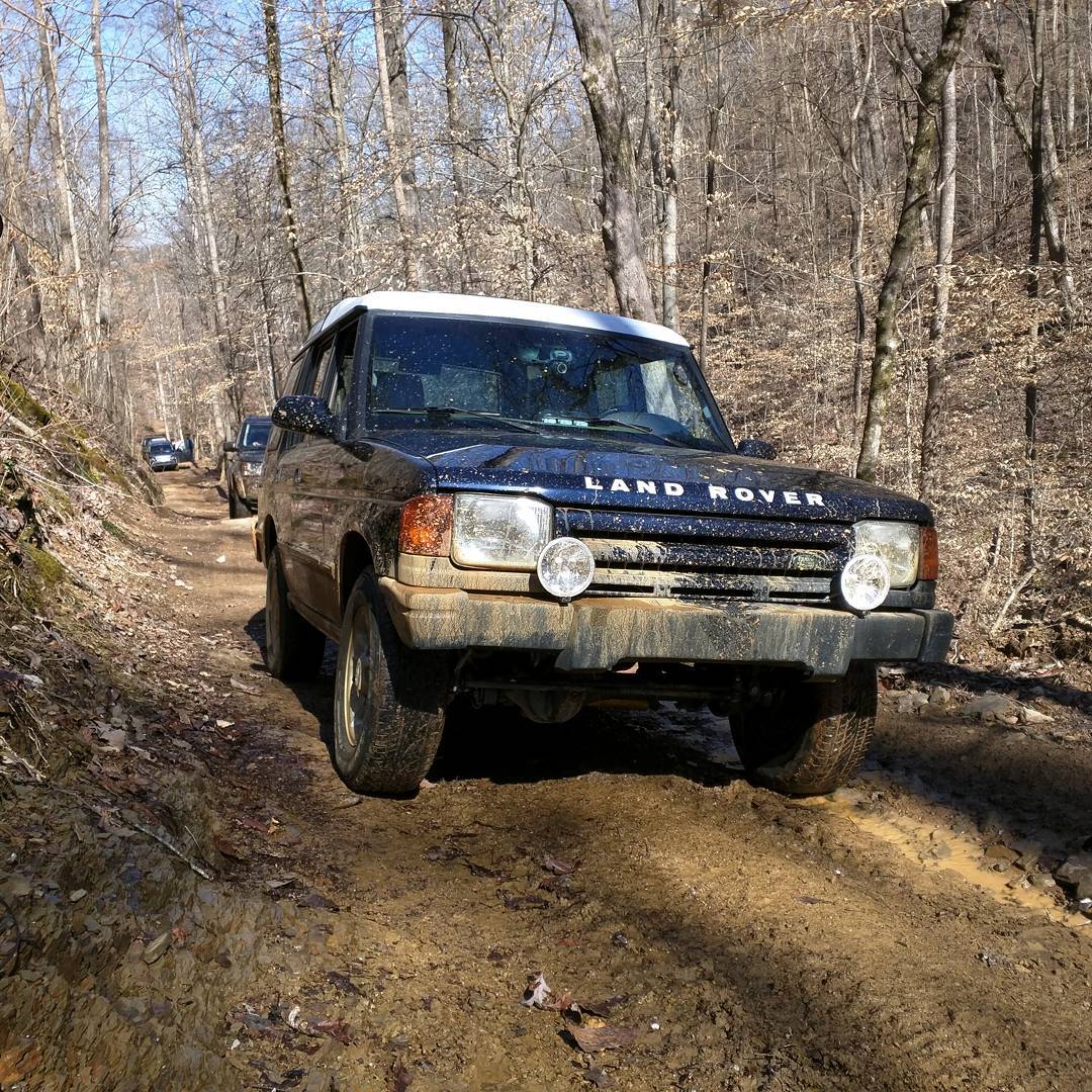
So here is my Land Rover. It's a mostly completely stock 1998 Discovery automatic with almost 200k miles on it. I've replaced most of the original suspension parts with new pieces and that has helped the truck considerably. It's had the typical problems, with shoddy wiring and leaky sunroofs. I've fixed most of the problems with the help of these message forums and the Land Rover community.
I didn't document pulling the motor, but the Land Rover Workshop manual has a great step by step procedure for doing this. The hardest part, in my opinion, was getting to the bolts holding the transmission bellhousing to the block and the four bolts that hold the torque converter to the flexplate. There's not a lot of room, so patience is key there. I found it helped to remove the upper intake manifold and plenum to get access to the bolts.
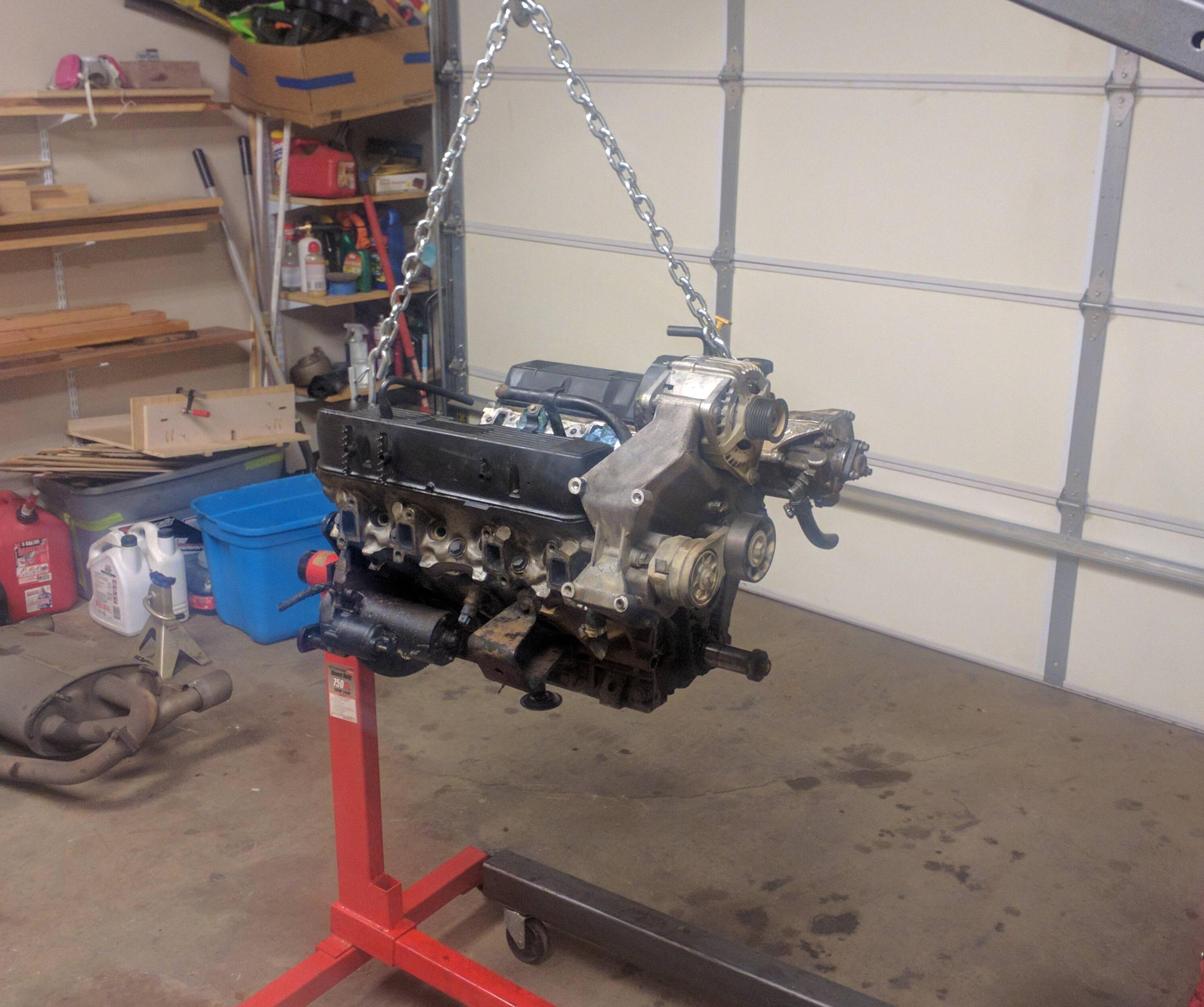
Here's my engine out and on the stand. I had already removed the oil sump, but this is essentially as it came out. Accessories still on!
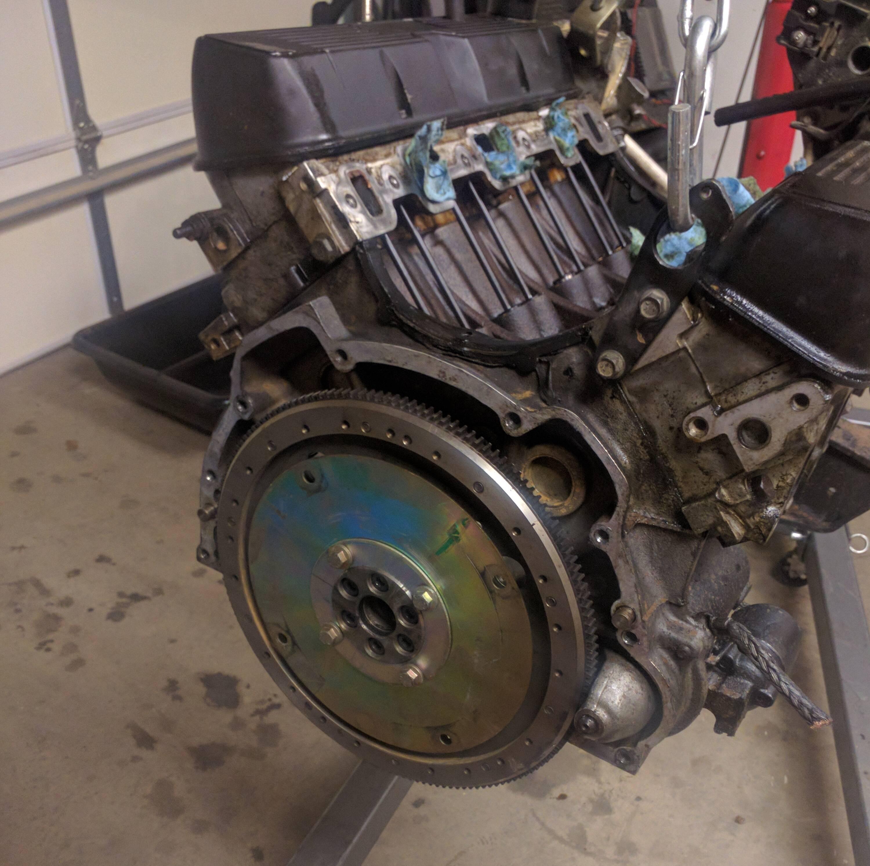
Here's the flexplate and flywheel... at least I think you still call them flywheels with automatic transmissions. This is my first and only automatic, so that part is new to me. I found it surprising how thin the flexplate is considering the entire torque of the motor goes through that thin plate and into the torque converter. On the outer edge of the flywheel are teeth that the starter engages in order to spin the engine. The four bolt holes on the outer edge of the shiny inner piece (flexplate) are where the torque converter bolts to. The four bolts on the inside are what bolts the flexplate to the flywheel. I didn't take a picture of it, but I used a 2x4 wedged inside the crank case so that the counterweights pressed against the 2x4 and stopped the engine front spinning. You'll need to do this to remove the four bolts holding the flexplate and flywheel on.
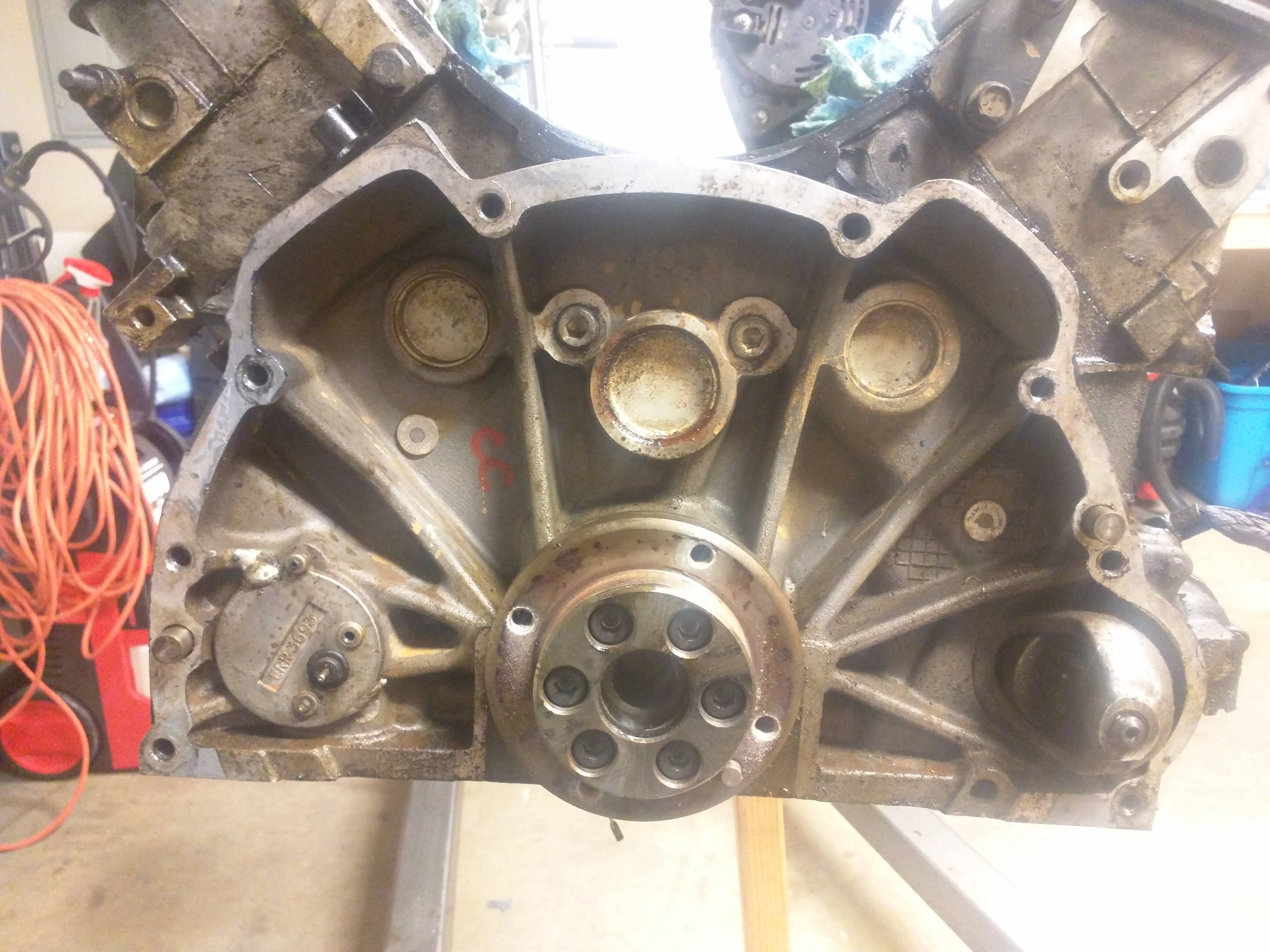
Here is the flexplate and flywheel removed. I had to use a small prybar and wedge around the outside and whack it with a rubber mallet to get it to come off. Center is the crankshaft. Above that, in the middle is the plug for the back of the camshaft. The mickey mouse ears on each side are what I assume plugs to clean the oil gallery for each lifter passage. I'm not sure I am competent enough to do that, so I doubt I will remove these. I'll put that firmly in the "maybe" category. Flanking the mickey mouse ears are plugs for the coolant passages called freeze plugs. These are sacrificial plugs that pop out if the coolant ever freezes. This way the plug is damaged and the block doesn't crack. The bottom left contains a sensor, which I will talk about in a minute and the bottom right is the starter.
This is what I am assuming is the crankshaft position sensor. On the flywheel there were little teeth sticking out of the front in pairs that went around in a large ring. This sensor detects the teeth and a missing pair in order to determine where the crankshaft is in its 360 degree rotation. I probably should have marked the flywheel and the crankshaft to keep a reference of their position, but I didn't think about it at the time. So upon reassembly I'll have to determine this. If anyone is interested in a picture of the backside of the flywheel and the teeth, i'll take a picture of it. Be sure not to bend the teeth when removing the motor as it can damage the sensor when you start the motor.
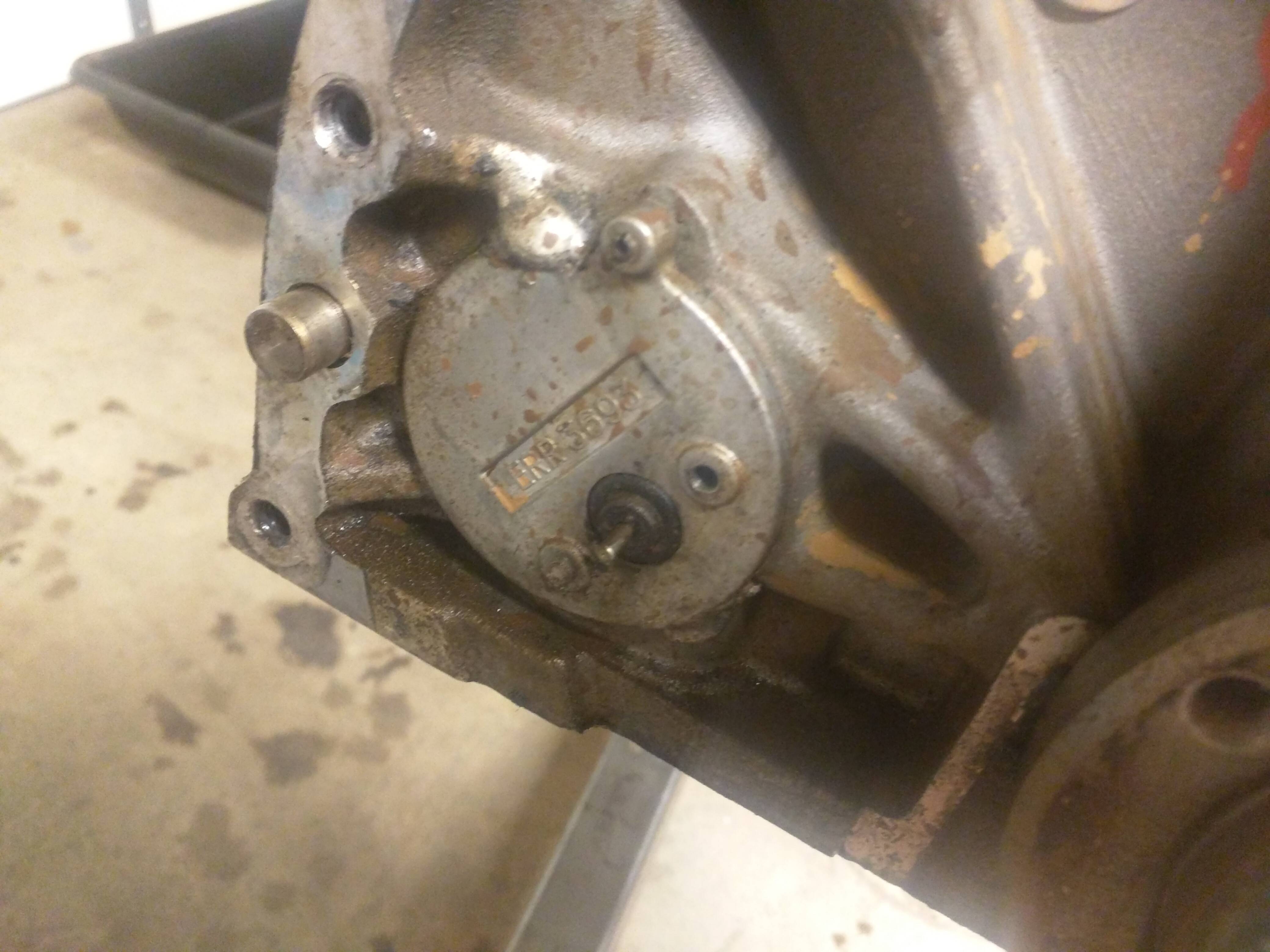
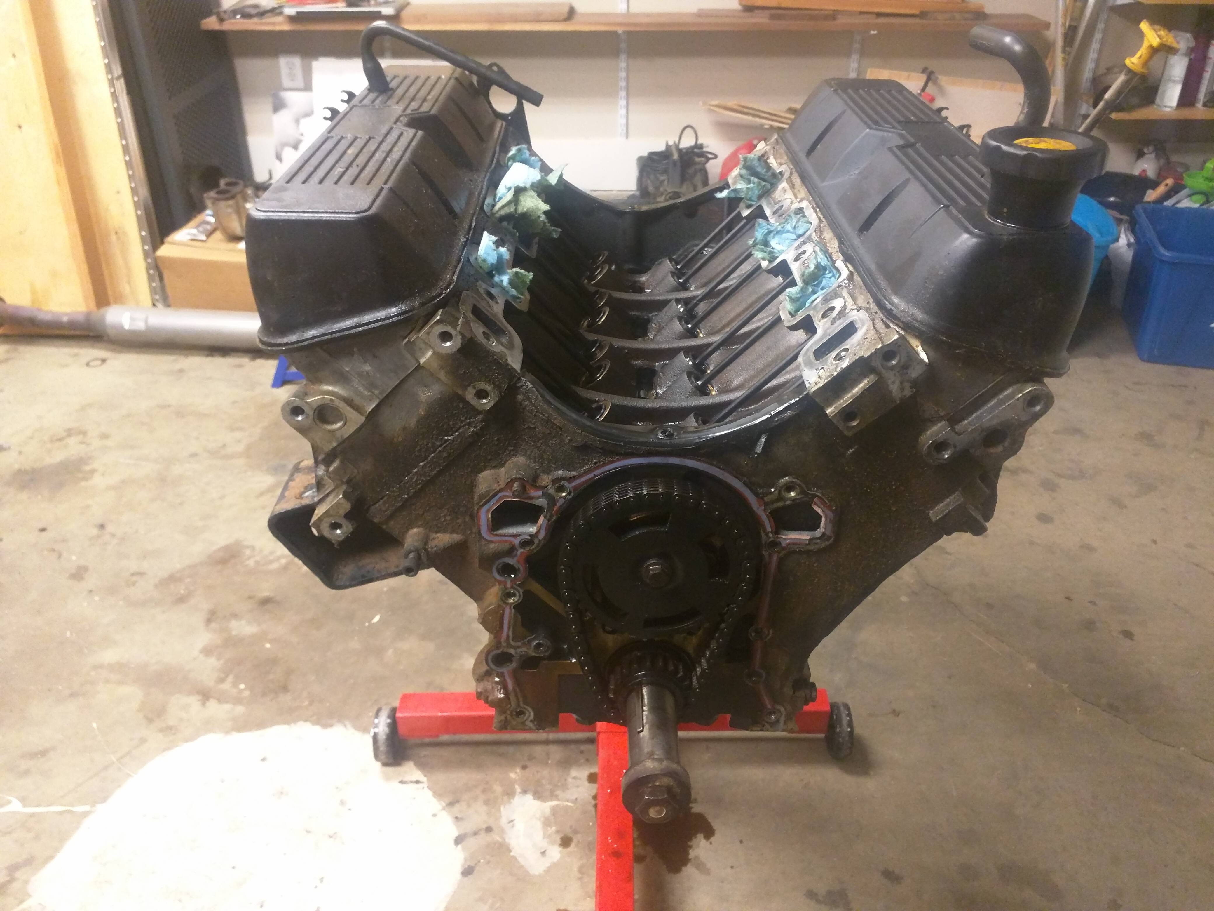
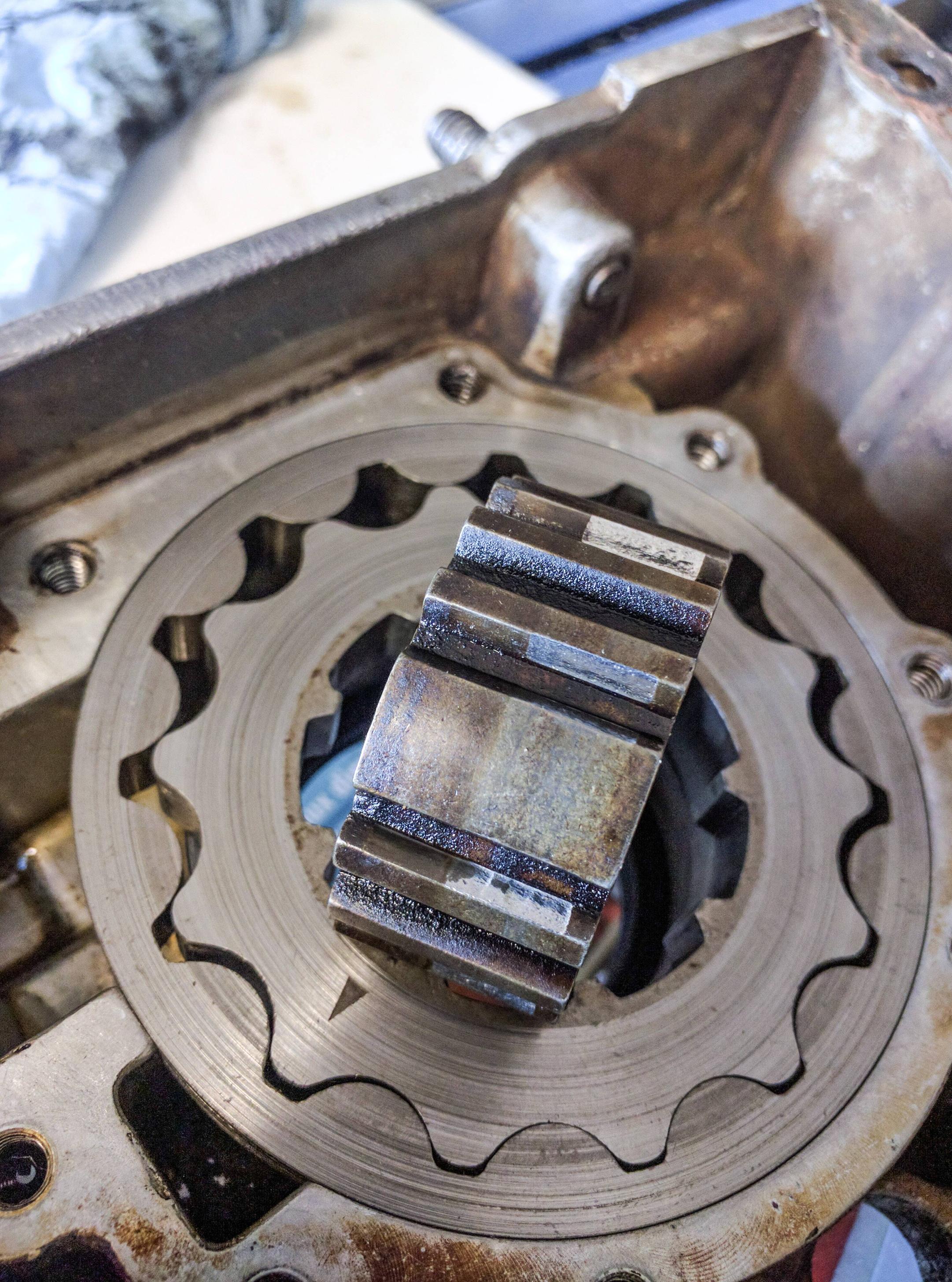
Here's the front of the motor, with the timing cover and waterpump removed. I also removed the alternator and belt tensioner bracket as well as the power steering bracket. Center large gear is the camshaft timing gear, under it the small gear is the crankshaft timing gear. Connecting the two is the timing chain, and mine was quite floppy. It probably should have been replaced like 50k miles ago. The two holes flanking the camshaft timing gear are for the water pump.
It's worth noting, you can get to the oil pump and timing chain with the engine still in the truck. There's plenty of room and everything is quite easy to get to. As you can see, my motor leaked from pretty much everywhere, so I had already planned on pulling the motor to help clean up everything. I had already moved the intake valley gasket to check out the cam and lifters prior to this picture.
I didn't document pulling the motor, but the Land Rover Workshop manual has a great step by step procedure for doing this. The hardest part, in my opinion, was getting to the bolts holding the transmission bellhousing to the block and the four bolts that hold the torque converter to the flexplate. There's not a lot of room, so patience is key there. I found it helped to remove the upper intake manifold and plenum to get access to the bolts.
Here's my engine out and on the stand. I had already removed the oil sump, but this is essentially as it came out. Accessories still on!
Here's the flexplate and flywheel... at least I think you still call them flywheels with automatic transmissions. This is my first and only automatic, so that part is new to me. I found it surprising how thin the flexplate is considering the entire torque of the motor goes through that thin plate and into the torque converter. On the outer edge of the flywheel are teeth that the starter engages in order to spin the engine. The four bolt holes on the outer edge of the shiny inner piece (flexplate) are where the torque converter bolts to. The four bolts on the inside are what bolts the flexplate to the flywheel. I didn't take a picture of it, but I used a 2x4 wedged inside the crank case so that the counterweights pressed against the 2x4 and stopped the engine front spinning. You'll need to do this to remove the four bolts holding the flexplate and flywheel on.
Here is the flexplate and flywheel removed. I had to use a small prybar and wedge around the outside and whack it with a rubber mallet to get it to come off. Center is the crankshaft. Above that, in the middle is the plug for the back of the camshaft. The mickey mouse ears on each side are what I assume plugs to clean the oil gallery for each lifter passage. I'm not sure I am competent enough to do that, so I doubt I will remove these. I'll put that firmly in the "maybe" category. Flanking the mickey mouse ears are plugs for the coolant passages called freeze plugs. These are sacrificial plugs that pop out if the coolant ever freezes. This way the plug is damaged and the block doesn't crack. The bottom left contains a sensor, which I will talk about in a minute and the bottom right is the starter.
This is what I am assuming is the crankshaft position sensor. On the flywheel there were little teeth sticking out of the front in pairs that went around in a large ring. This sensor detects the teeth and a missing pair in order to determine where the crankshaft is in its 360 degree rotation. I probably should have marked the flywheel and the crankshaft to keep a reference of their position, but I didn't think about it at the time. So upon reassembly I'll have to determine this. If anyone is interested in a picture of the backside of the flywheel and the teeth, i'll take a picture of it. Be sure not to bend the teeth when removing the motor as it can damage the sensor when you start the motor.
Here's the front of the motor, with the timing cover and waterpump removed. I also removed the alternator and belt tensioner bracket as well as the power steering bracket. Center large gear is the camshaft timing gear, under it the small gear is the crankshaft timing gear. Connecting the two is the timing chain, and mine was quite floppy. It probably should have been replaced like 50k miles ago. The two holes flanking the camshaft timing gear are for the water pump.
It's worth noting, you can get to the oil pump and timing chain with the engine still in the truck. There's plenty of room and everything is quite easy to get to. As you can see, my motor leaked from pretty much everywhere, so I had already planned on pulling the motor to help clean up everything. I had already moved the intake valley gasket to check out the cam and lifters prior to this picture.
Last edited by xathor; 06-08-2016 at 01:43 PM.
#3
06-08-2016, 01:59 PM
Off with the valve cover gaskets. Odd that they chose an 8mm 12pt bolt here. Not a socket I use very often so I had to go digging to find it. You can see that the previous owner didn't change the oil very often. There was gunk and buildup everywhere.
I took the rocker arms off by loosening the center two bolts first, then the outer two, then going back to the centers and loosening them some more. The idea here is to not put a lot of pressure on the rocker shaft. I've never experienced it, but I hear they can warp quite easily. Just take your time and undo the four bolts slowly from center out.
I marked the passenger side rocker shaft with a red zip tie in order to ensure that I don't get them mixed up. They might be marked from the factory, but I can't see under all the gunk that has built up on all the parts. Change your oil often or you'll get this nasty buildup.
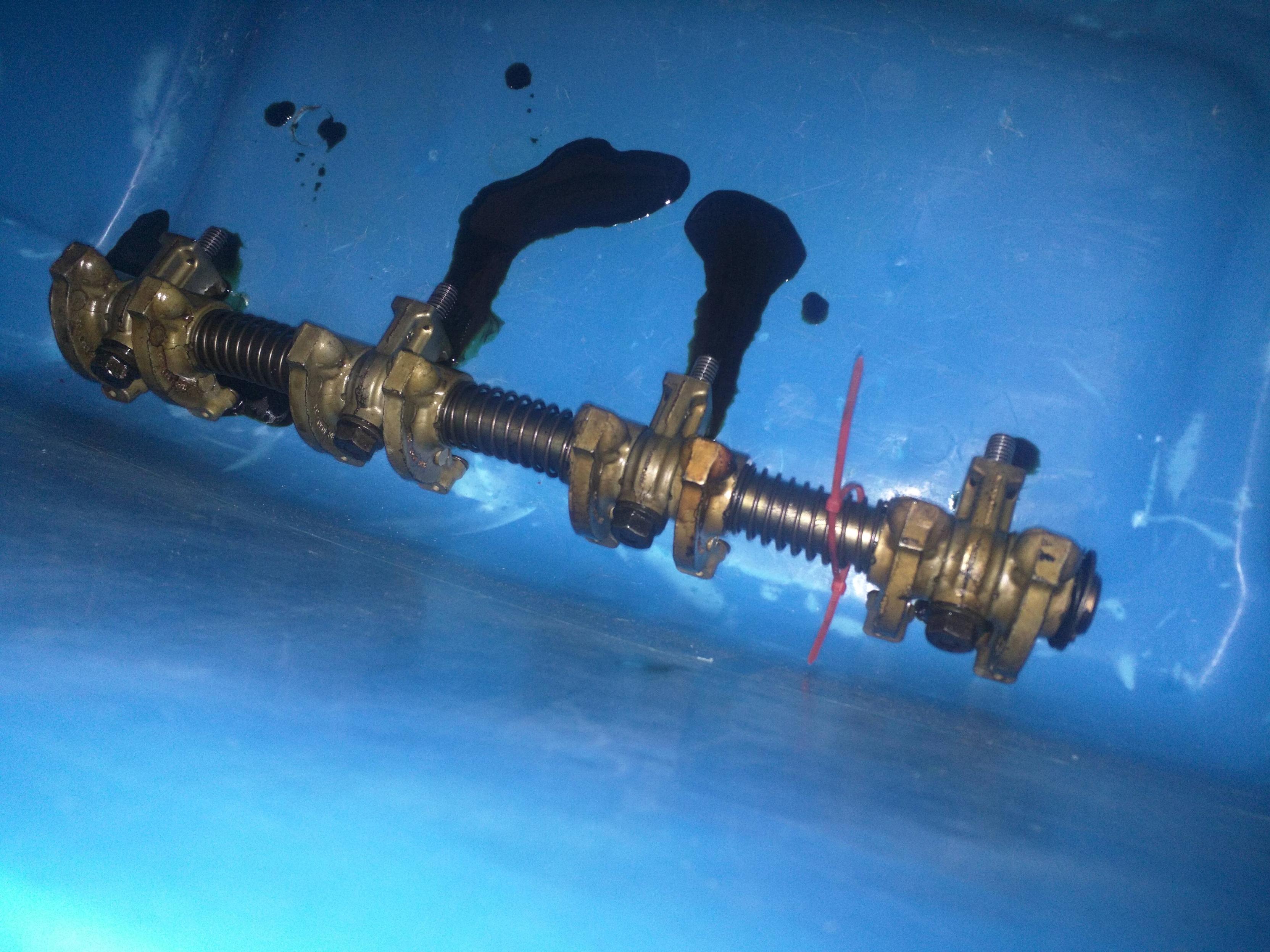
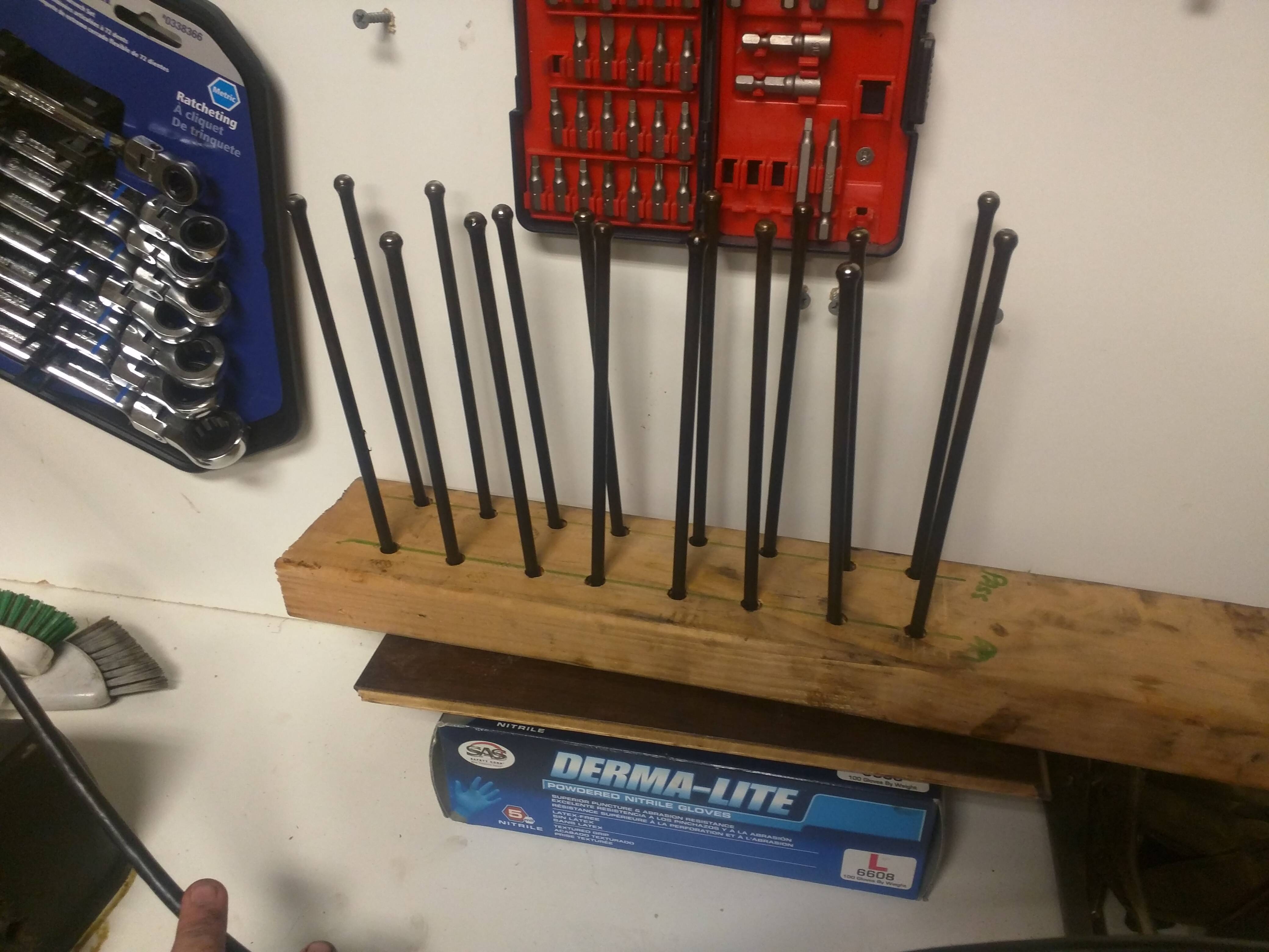
Once the rockers are off, the pushrods are free to be removed. In order to document this and keep them all in order, I drilled sixteen 3/8 inch holes in a 2x4 and marked front and passenger/driver side. First inspection, all of the pushrods look straight. Hopefully I can re-use them.
Once the pushrods are removed, use a magnet and pull the lifters out slightly until you can get a hold of them. Sometimes they have a little bit of buildup and they refuse to come out. If they do, spin them a little bit and try again. Eventually they will come out. Be as gentle as you can so that you don't scratch or score the bore of the area they come from.
Once I laid all of mine out... Oh my, they are rekt.
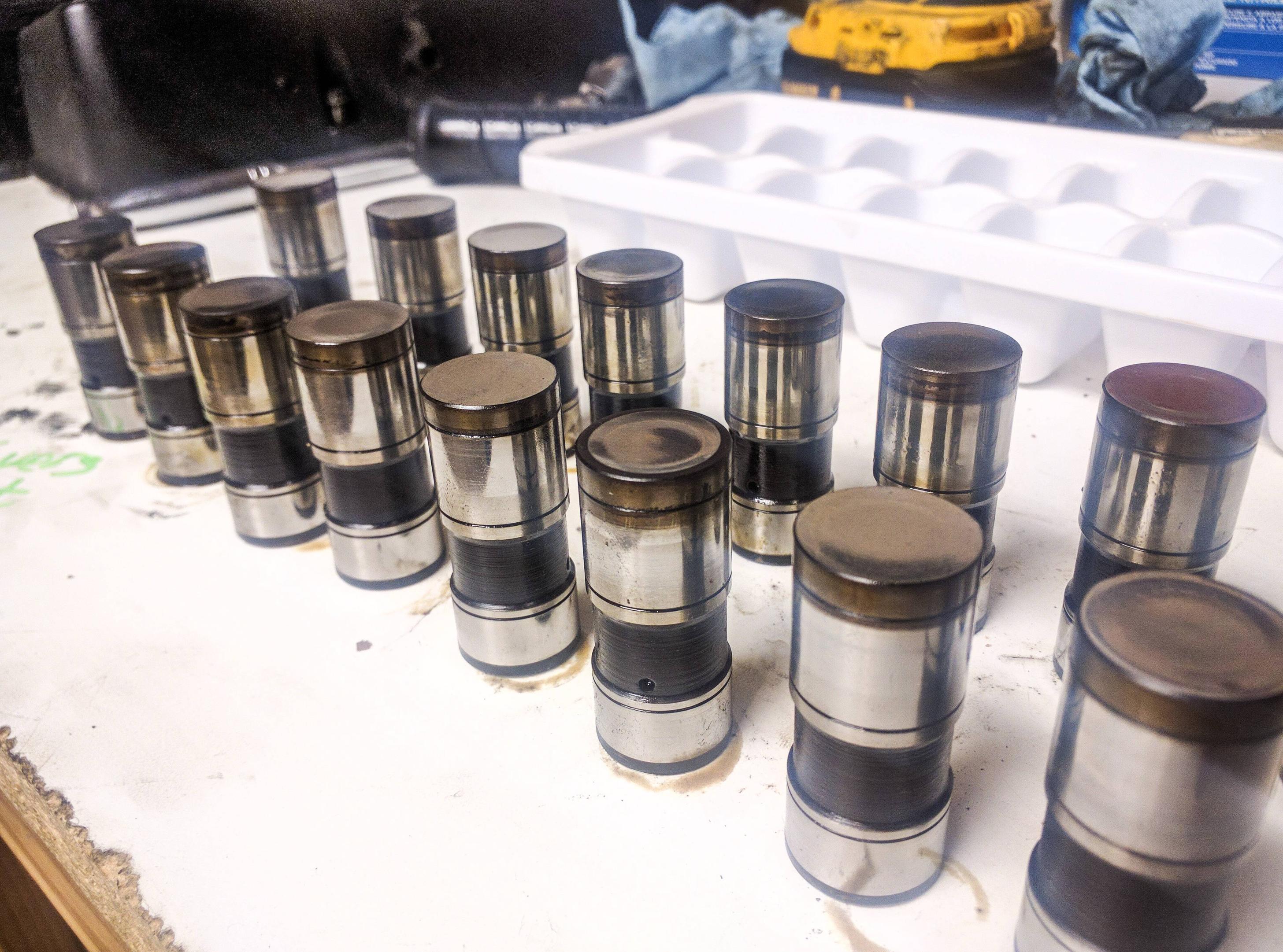
Some of them have minor scuffs, others have a slight concave face. One looks like an asteroid hit it and another has some galling where the face of the lifter has been removed. These are flat tappet lifters... so the face is supposed to be flat.
This engine came with hydraulic lifters, meaning some of the engine oil pressure is pushed inside of the lifter in order to inflate them. This causes the lifter to take up the slack between the cam, lifter, pushrod, rocker arm and valve stem. The idea here is to account for some wear, valve stretch and create a maintenance free engine. When people refer to "noisy lifters" they are referring to this part and it typically means that the lifter is not inflating correctly. This usually means either the lifter is worn, like mine... or possibly the lifter is gummed up or "sticky". Lifters and cams need to be replaced together, as they are a wear item. Always replace these components together. If you aren't replacing them, use an ice cube tray and put the lifters in there in order to keep them organized. They must be returned from where the came!
Turns out i'll be replacing the cam and lifters.
I took the rocker arms off by loosening the center two bolts first, then the outer two, then going back to the centers and loosening them some more. The idea here is to not put a lot of pressure on the rocker shaft. I've never experienced it, but I hear they can warp quite easily. Just take your time and undo the four bolts slowly from center out.
I marked the passenger side rocker shaft with a red zip tie in order to ensure that I don't get them mixed up. They might be marked from the factory, but I can't see under all the gunk that has built up on all the parts. Change your oil often or you'll get this nasty buildup.
Once the rockers are off, the pushrods are free to be removed. In order to document this and keep them all in order, I drilled sixteen 3/8 inch holes in a 2x4 and marked front and passenger/driver side. First inspection, all of the pushrods look straight. Hopefully I can re-use them.
Once the pushrods are removed, use a magnet and pull the lifters out slightly until you can get a hold of them. Sometimes they have a little bit of buildup and they refuse to come out. If they do, spin them a little bit and try again. Eventually they will come out. Be as gentle as you can so that you don't scratch or score the bore of the area they come from.
Once I laid all of mine out... Oh my, they are rekt.
Some of them have minor scuffs, others have a slight concave face. One looks like an asteroid hit it and another has some galling where the face of the lifter has been removed. These are flat tappet lifters... so the face is supposed to be flat.
This engine came with hydraulic lifters, meaning some of the engine oil pressure is pushed inside of the lifter in order to inflate them. This causes the lifter to take up the slack between the cam, lifter, pushrod, rocker arm and valve stem. The idea here is to account for some wear, valve stretch and create a maintenance free engine. When people refer to "noisy lifters" they are referring to this part and it typically means that the lifter is not inflating correctly. This usually means either the lifter is worn, like mine... or possibly the lifter is gummed up or "sticky". Lifters and cams need to be replaced together, as they are a wear item. Always replace these components together. If you aren't replacing them, use an ice cube tray and put the lifters in there in order to keep them organized. They must be returned from where the came!
Turns out i'll be replacing the cam and lifters.
#4
06-08-2016, 02:06 PM
Oh, I skipped over something important.
Oil pump.
My original intent was to just replace the oil pump as I had assumed that my oil pump had either cracked or was just worn.
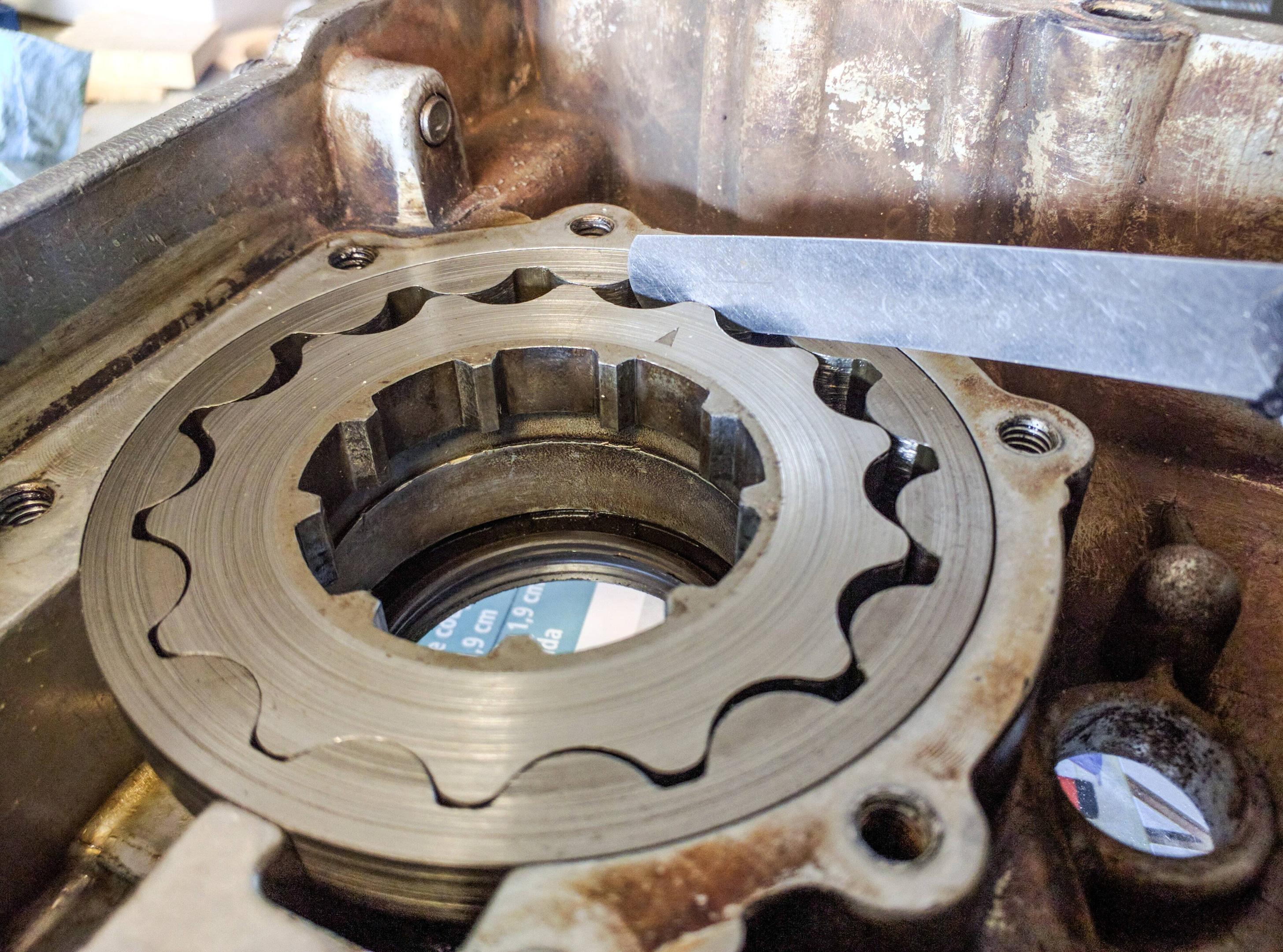
I grabbed the high-end spec feeler gauge for measuring between the lobes and it cleared with minimal drag. My oil pump wasn't cracked, but quite worn.
The face between the gears and the cover was within spec, but had some scoring.
The gear that went on the crankshaft that spun the oil pump was badly worn.
I'm going to do a more detailed write up on inspecting the oil pump and how to measure its clearances. An oil pump replacement kit is quite cheap and can be done with the engine still in, so it's worth doing if you think you might have an oil pressure problem.
Oil pump.
My original intent was to just replace the oil pump as I had assumed that my oil pump had either cracked or was just worn.
I grabbed the high-end spec feeler gauge for measuring between the lobes and it cleared with minimal drag. My oil pump wasn't cracked, but quite worn.
The face between the gears and the cover was within spec, but had some scoring.
The gear that went on the crankshaft that spun the oil pump was badly worn.
I'm going to do a more detailed write up on inspecting the oil pump and how to measure its clearances. An oil pump replacement kit is quite cheap and can be done with the engine still in, so it's worth doing if you think you might have an oil pressure problem.
#5
06-08-2016, 02:18 PM
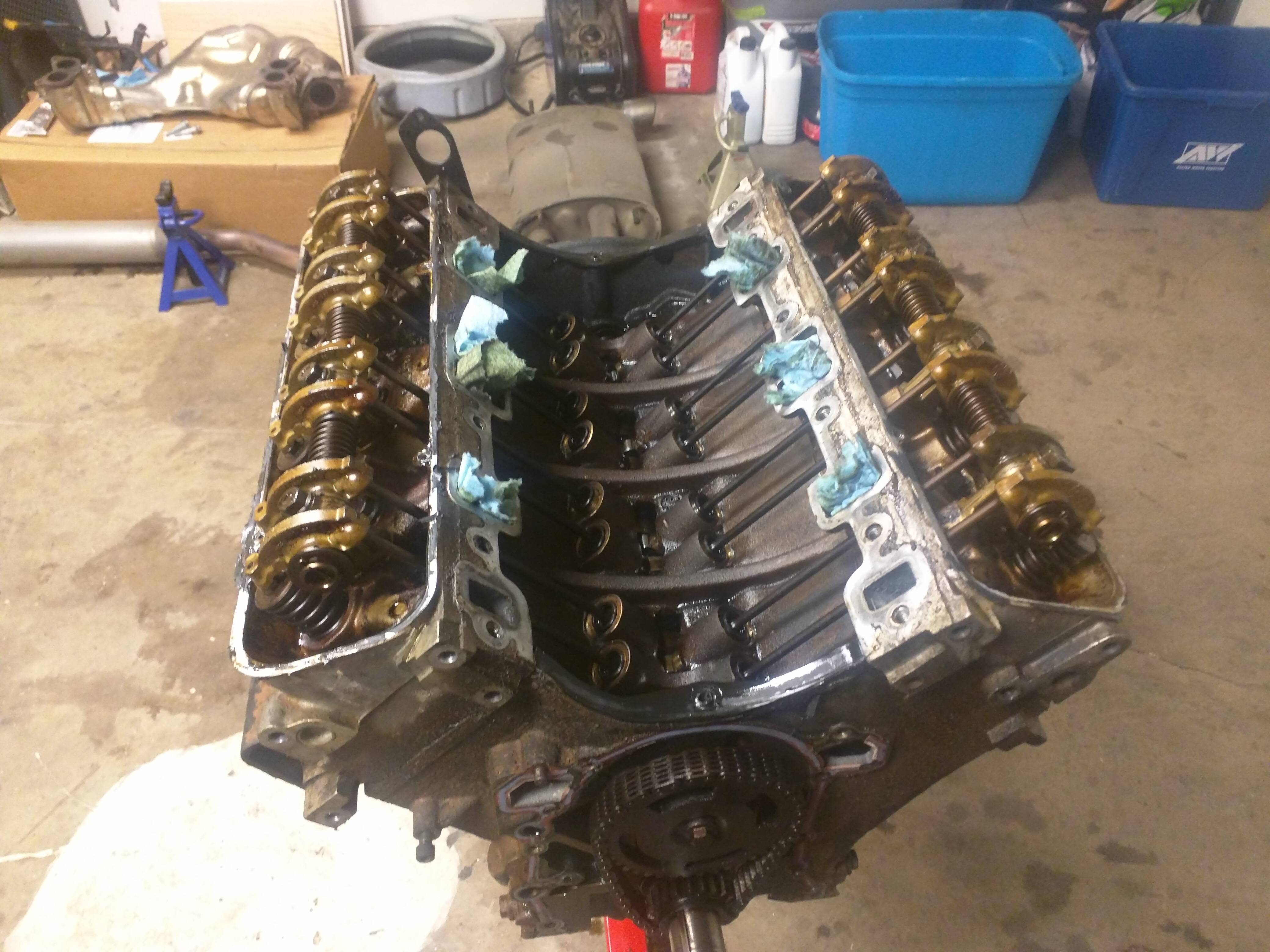
I followed the order in which the workshop manual states to loosen the head bolts. What it doesn't tell you is how to keep the engine stand from following you around as you put the largest breaker bar you own on the bolt. I felt like I was doing a dance with the motor and my now oil covered garage floor. I eventually prevailed.
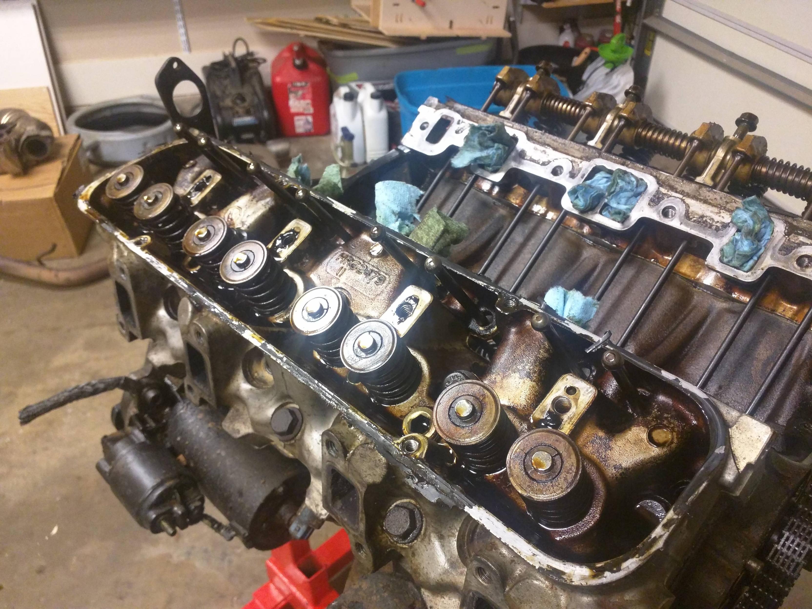
I lightly hit the edge of the head with a very soft rubber mallet in order to loosen up the heads. I didn't take any pictures of this, but that's mainly because my gloves were covered in oil. Once I got the heads off... I was shocked!
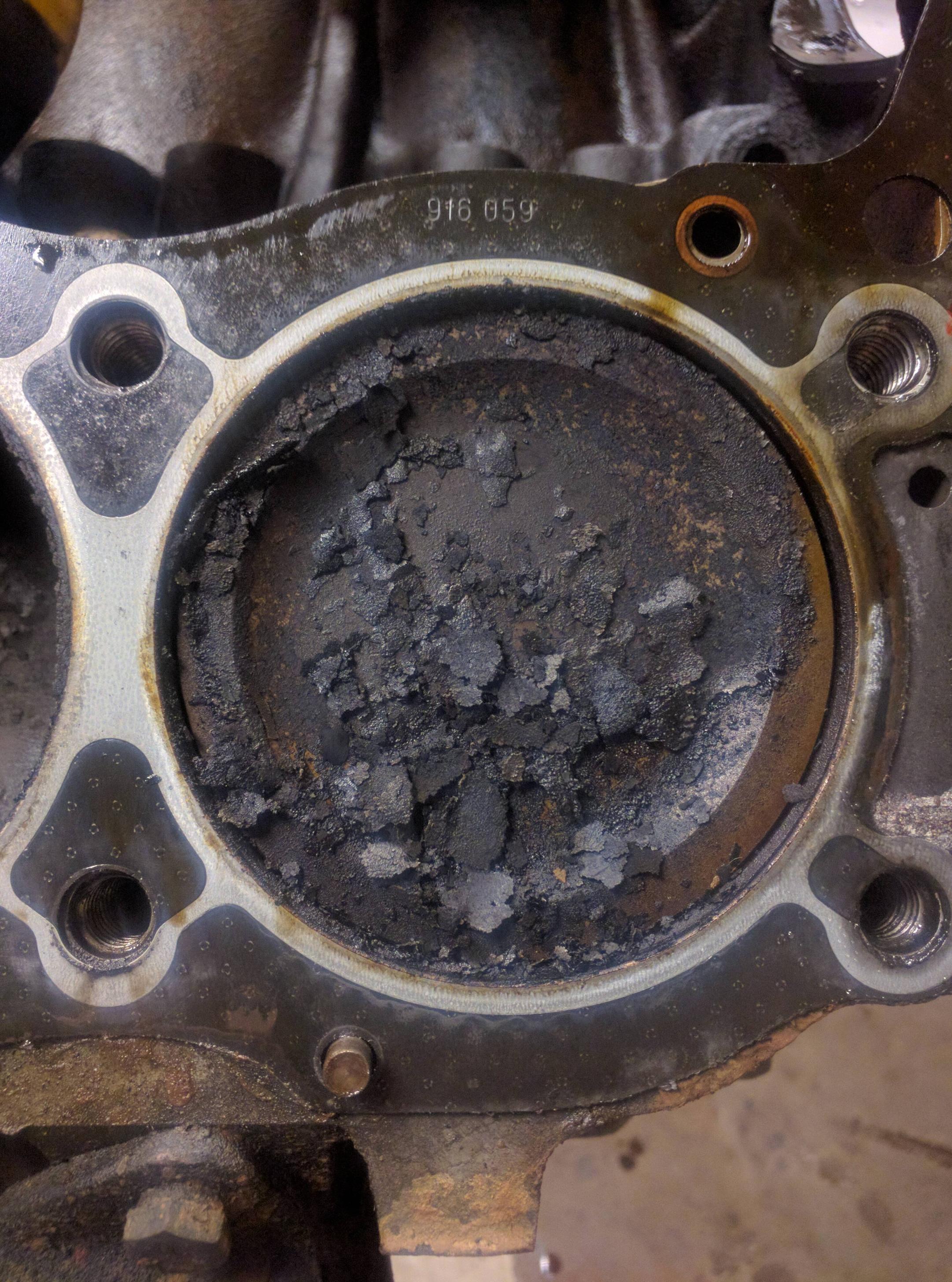
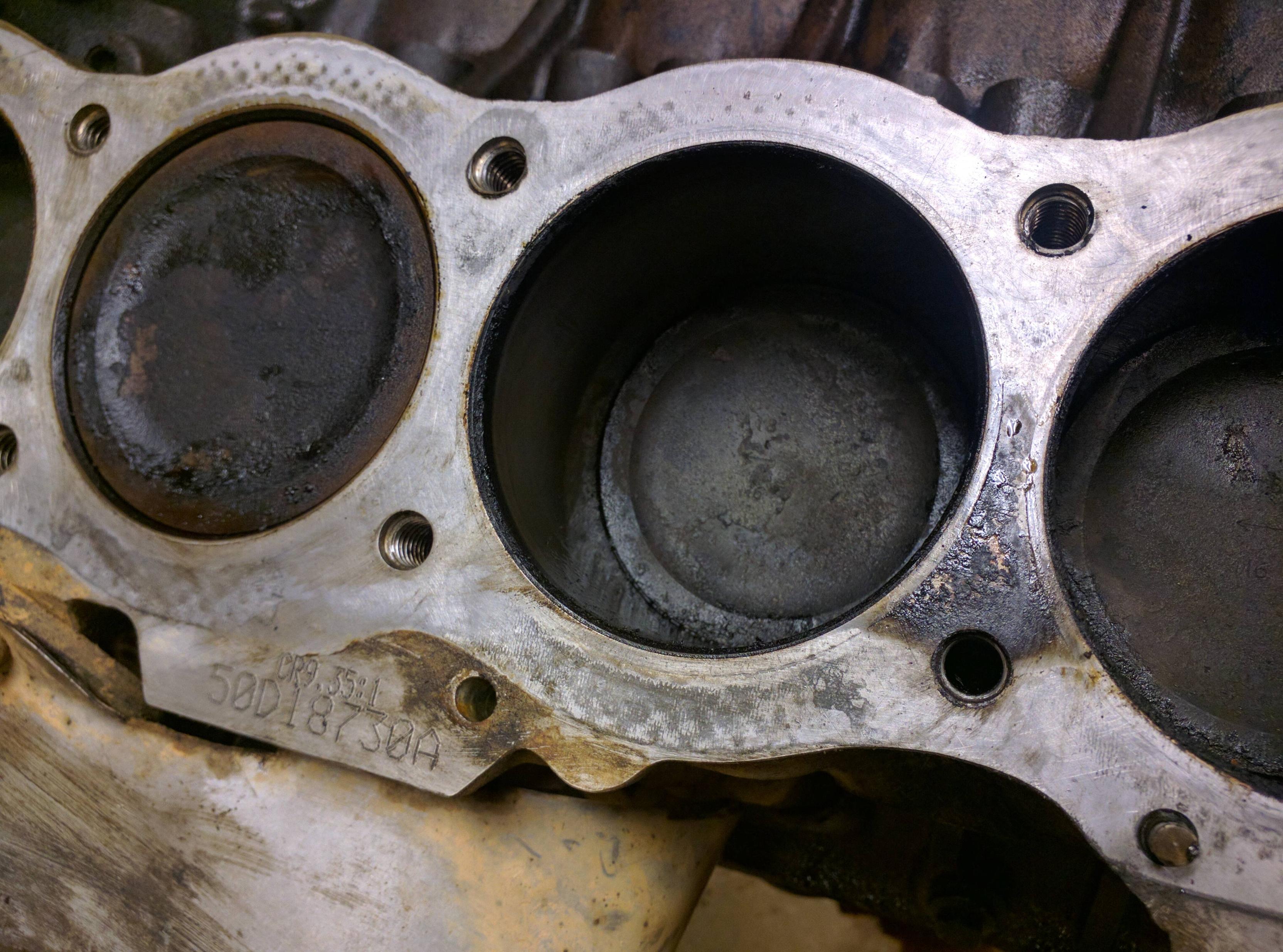
All of the bores were full of this flaky carbon deposit. I assume I knocked this off of the heads when I removed the heads. I've never seen this before and I didn't see any hint of carbon deposits on the pistons when I looked down the spark plug hole.
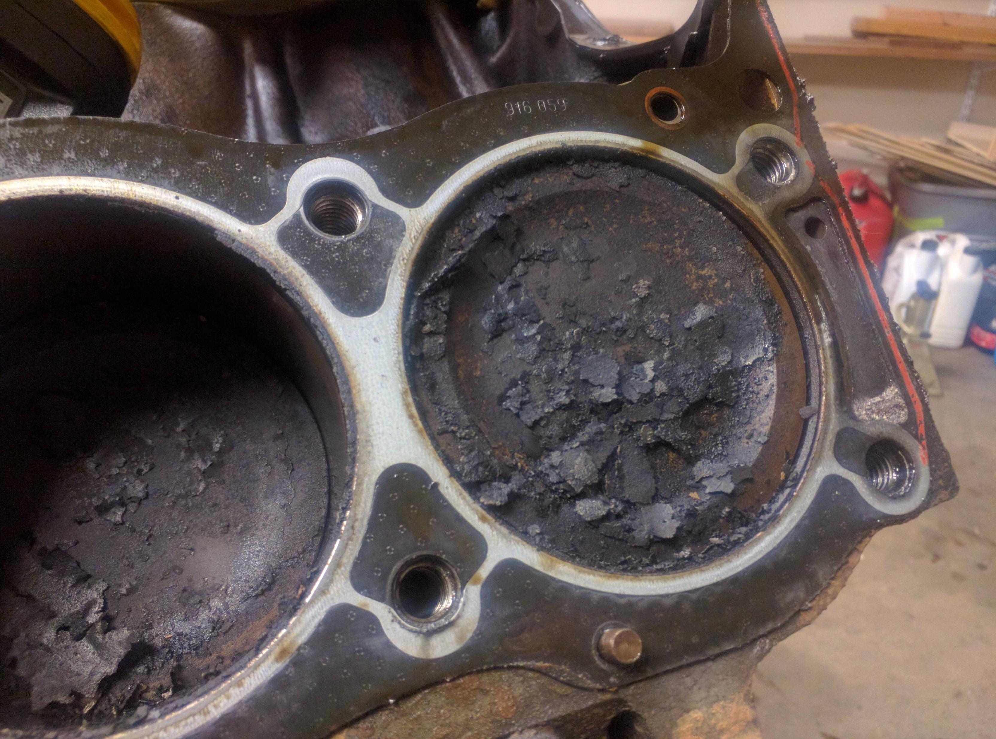
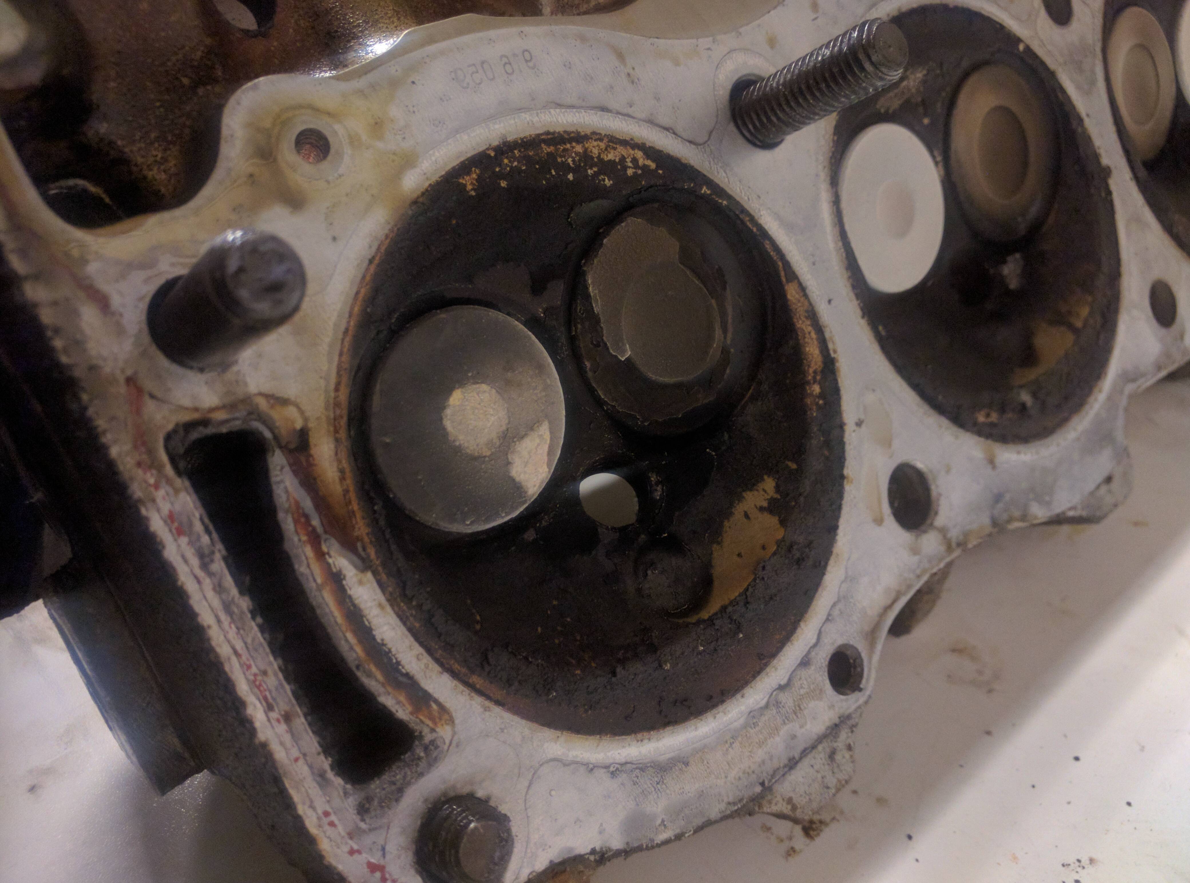
This baffled me. I've never seen this much carbon build up in a motor, much less loose like this. I vacuumed it out with my shop vac. The heads had the same build up. I'm wondering if the previous owner used cheap gas. I've had the truck for a little while now and only use BP/Mapco gas stations.
I removed the headgaskets and oh my... I'm not sure what caused this. The headgasket looked good... Possibly a previously blown head gaskest, but I cant imagine someone not cleaning the surface well before putting a new gasket on. Maybe a slightly leaky gasket? Either way, it'll be fixed soon enough.
I lightly hit the edge of the head with a very soft rubber mallet in order to loosen up the heads. I didn't take any pictures of this, but that's mainly because my gloves were covered in oil. Once I got the heads off... I was shocked!
All of the bores were full of this flaky carbon deposit. I assume I knocked this off of the heads when I removed the heads. I've never seen this before and I didn't see any hint of carbon deposits on the pistons when I looked down the spark plug hole.
This baffled me. I've never seen this much carbon build up in a motor, much less loose like this. I vacuumed it out with my shop vac. The heads had the same build up. I'm wondering if the previous owner used cheap gas. I've had the truck for a little while now and only use BP/Mapco gas stations.
I removed the headgaskets and oh my... I'm not sure what caused this. The headgasket looked good... Possibly a previously blown head gaskest, but I cant imagine someone not cleaning the surface well before putting a new gasket on. Maybe a slightly leaky gasket? Either way, it'll be fixed soon enough.
#6
06-08-2016, 02:29 PM
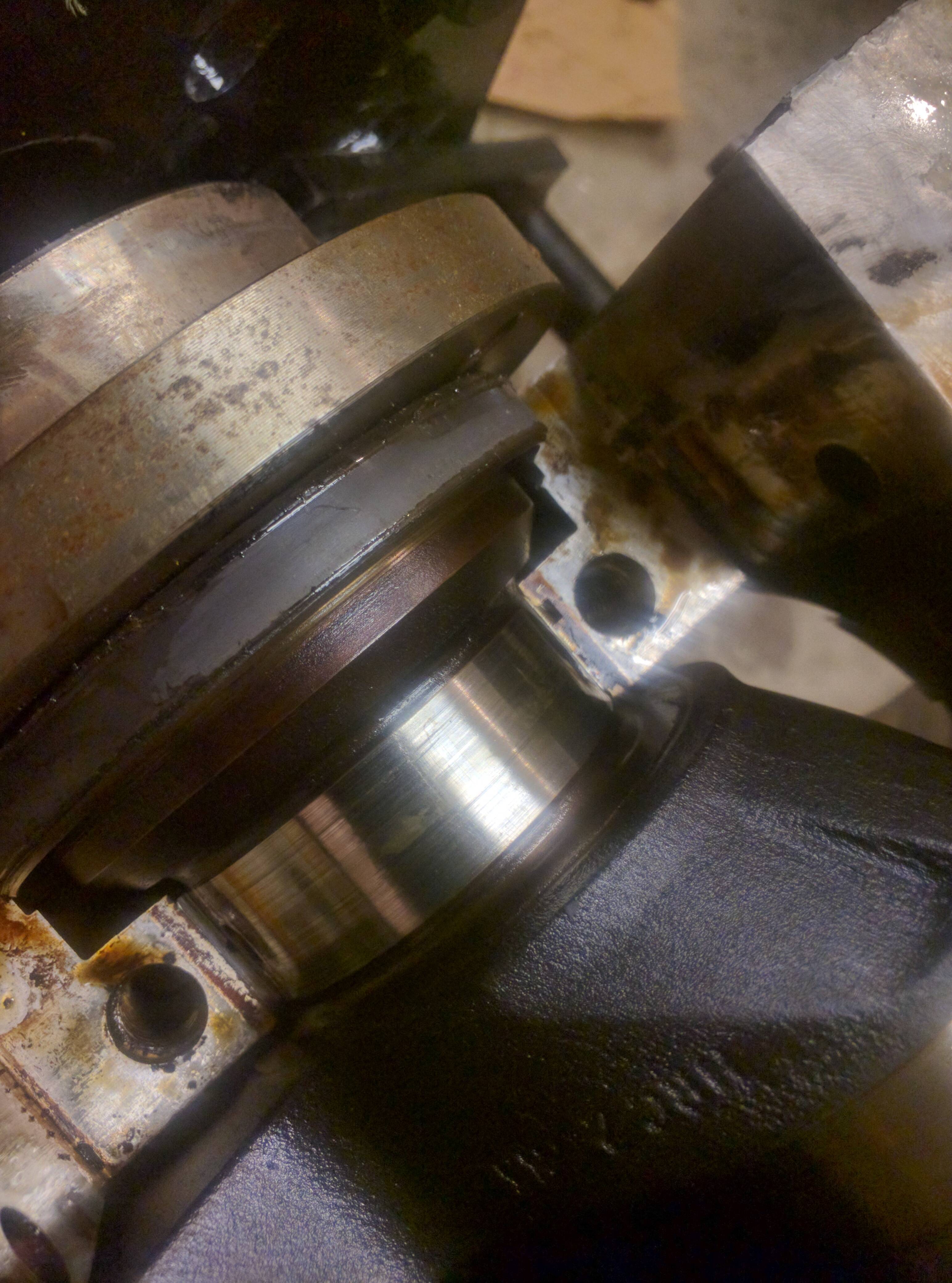
I got eager to see the rest of what I assumed was great carnage. SInce my oil pump wasn't THAT worn, I assumed the bearings must be worn. I popped a rod cap off and took a look.
Well... dang. Quite worn. They look normal for a high mileage motor that had a high dirt/oil mixture.
As for the crankshaft rod journals, I can run my finger of them and feel not only some ridges but also peaks and valleys. So, looks like some machine work is my future. This increases the price of the rebuild significantly, although I don't know what that cost will be.
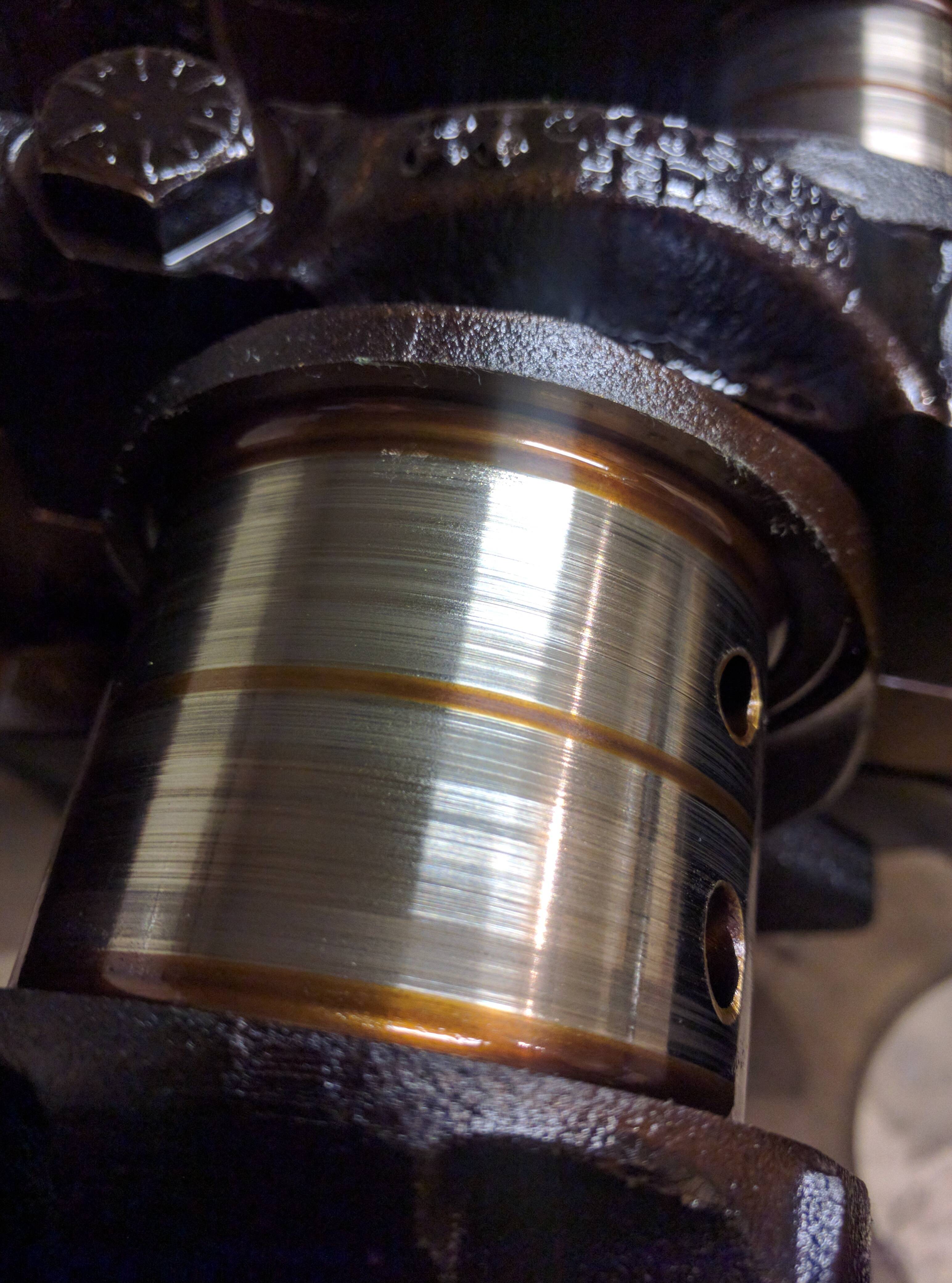
I don't own a set of outside micrometers, so I may have to buy a set. This is kind of cost prohibitive for a DIY rebuild. I've found some cheap sets on Amazon that have good reviews. I may purchase a set if I can't get a set to borrow. The idea here is to measure the journals to see how out of spec it is. Soon as I get a set, I'll do a full writeup of that procedure.
So now you are all caught up to where I am.
I intend of putting as much detail in this as I can for the reasons mentioned in my first post.
Well... dang. Quite worn. They look normal for a high mileage motor that had a high dirt/oil mixture.
As for the crankshaft rod journals, I can run my finger of them and feel not only some ridges but also peaks and valleys. So, looks like some machine work is my future. This increases the price of the rebuild significantly, although I don't know what that cost will be.
I don't own a set of outside micrometers, so I may have to buy a set. This is kind of cost prohibitive for a DIY rebuild. I've found some cheap sets on Amazon that have good reviews. I may purchase a set if I can't get a set to borrow. The idea here is to measure the journals to see how out of spec it is. Soon as I get a set, I'll do a full writeup of that procedure.
So now you are all caught up to where I am.
I intend of putting as much detail in this as I can for the reasons mentioned in my first post.
#7
06-08-2016, 03:29 PM

#9
06-08-2016, 07:52 PM

#10
06-09-2016, 10:08 AM
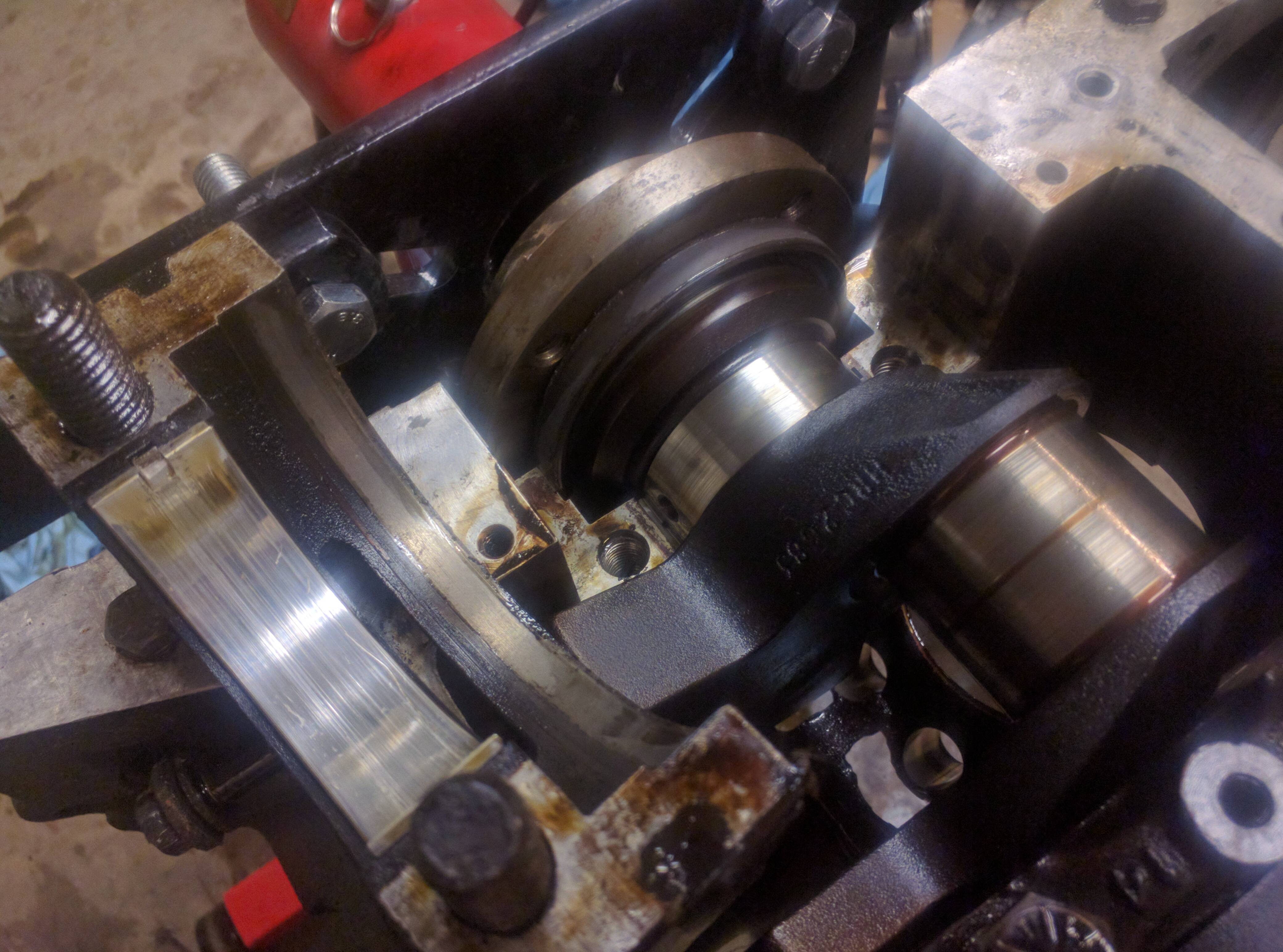
Got a little bit done yesterday, my goal was to remove the crankshaft from the block and check the main bearings.
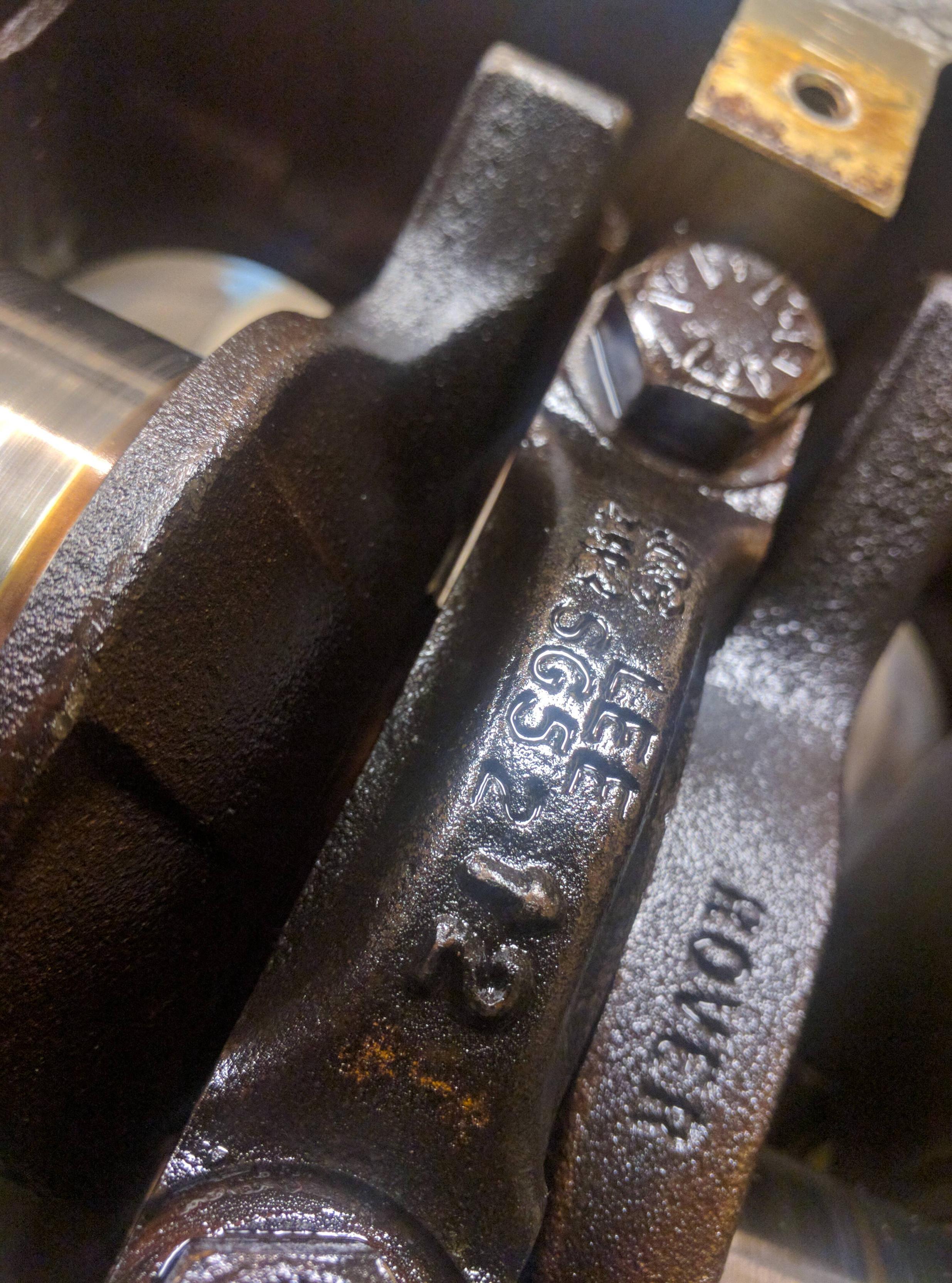
Starting at the center bearing, follow the same procedure for removing the head bolts. Center out, a little at a time. It helps to have an enormous breaker bar. I got my breaker bar from Autozone. These bolts are 19mm, if I remember correctly.
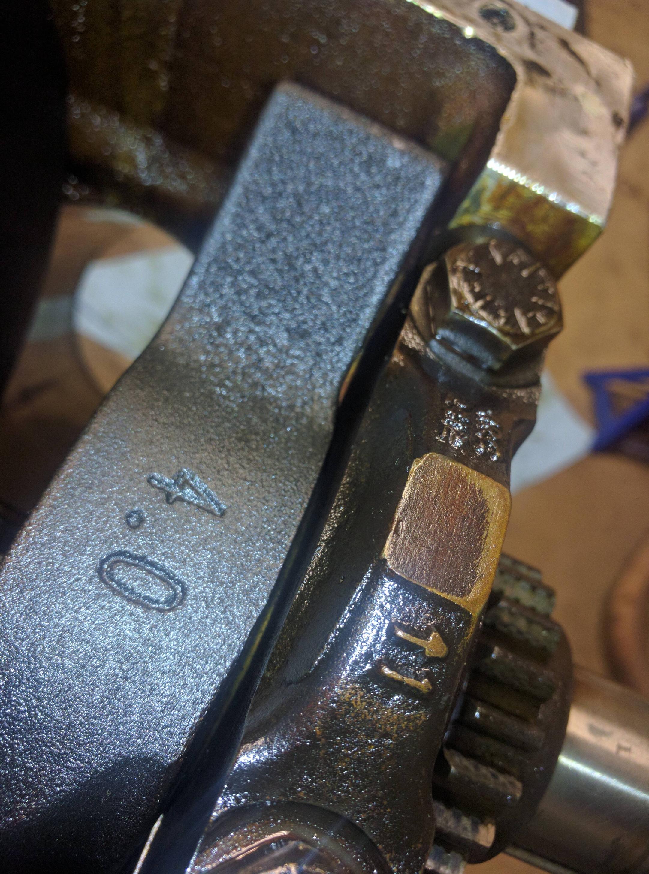
The bearing caps have to go back where they came from. Luckily someone was nice enough to cast in a number and the direction in which they face. Arrows always point to the front of the motor.
Here's the 2nd one...
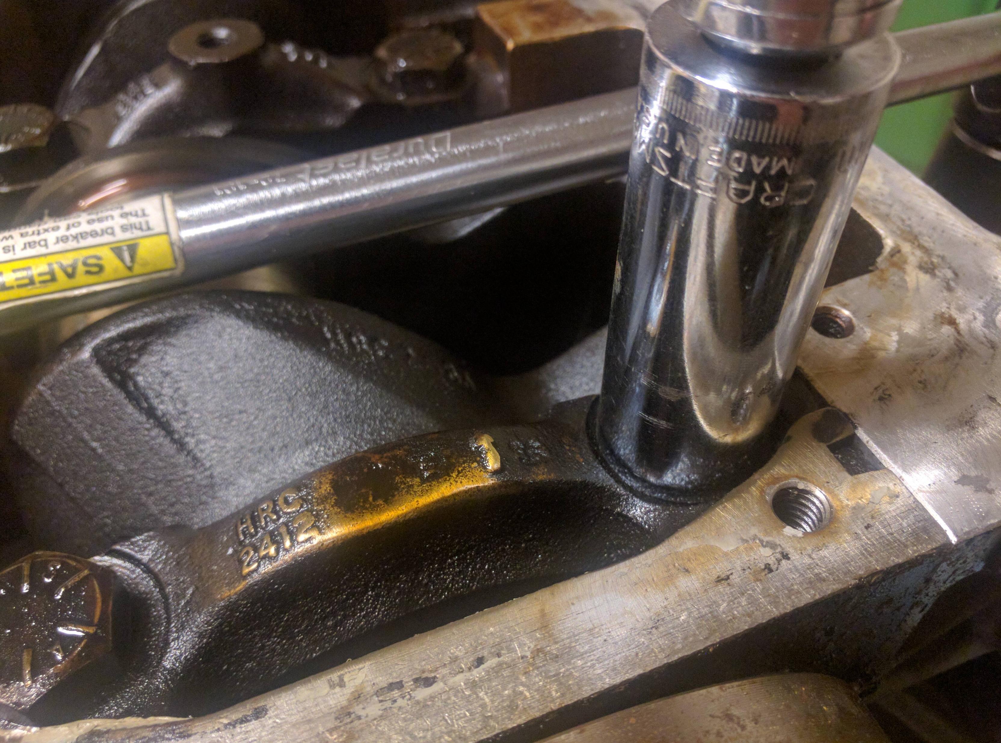
The rear main bearing is shrouded a little bit by the casting. I couldn't get my big 1/2 inch drive short 19mm in there, so I had to use this 3/8 inch tall 19mm socket. Always use the shortest socket you can to make sure you don't round off the top of the bolt heads.
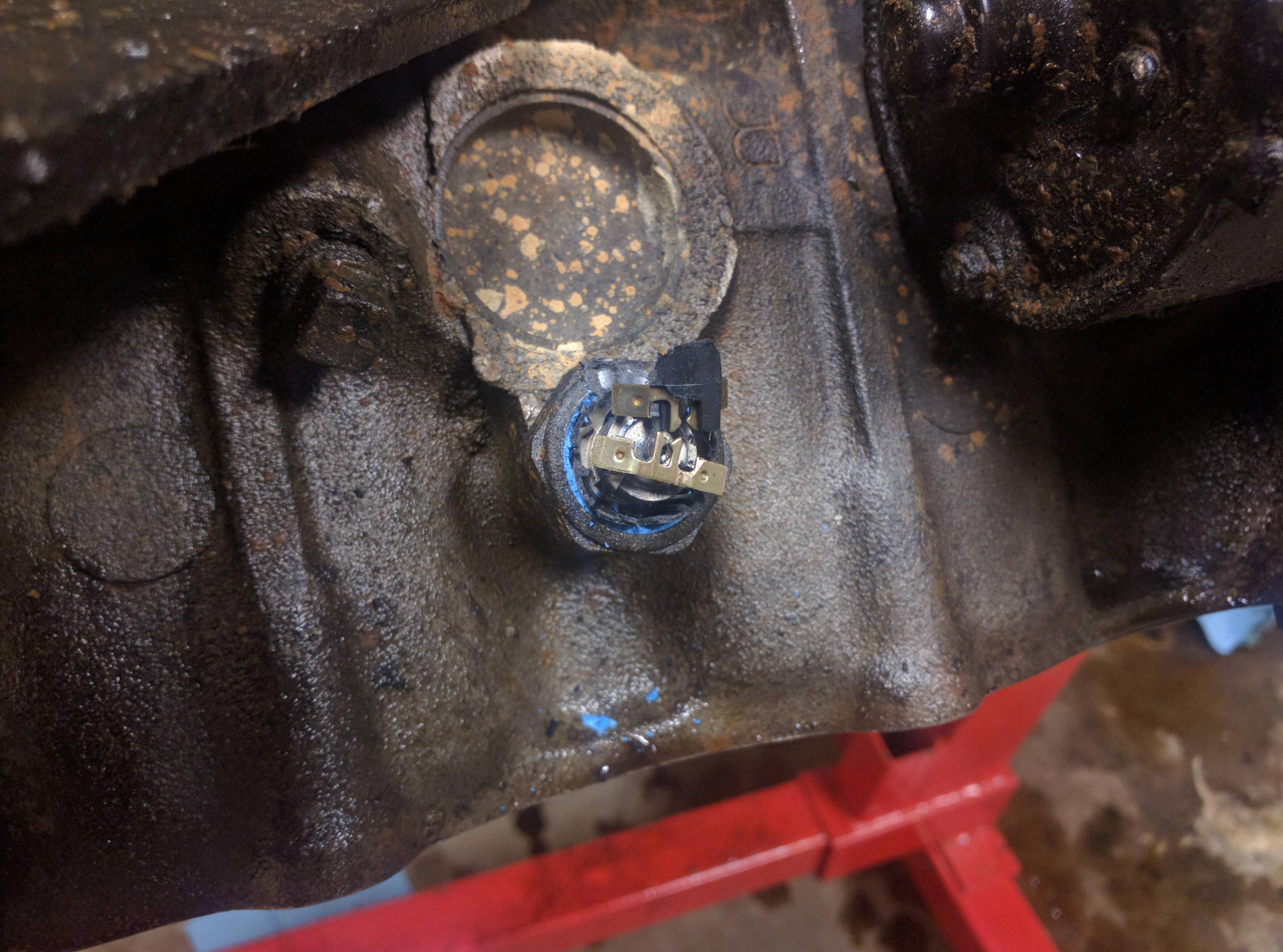
I had neglected to remove my starter, mainly because I can't find my 8mm. I have an 8mm 1/4 inch drive that I totally sheared the 1/4 inch to 3/8 inch adapter on. I ended up jamming a T55 in there and that worked, except for I totally destroyed what I am assuming is a knock sensor. Oops. ...Oh my, that's an expensive part. Don't be like me, remove the knock sensor first. Anyone got a used knock sensor laying around?
The rear main bearing side bolt next to the starter is also a 8mm. Pesky thing.
So there's a trick to getting these bearing caps out. Once you have loosened all of the bolts, take the two large bolts on the top and pull them out slightly until you can get a good grip on them. This will give you something to hold on to when you pull the cap off. If you can't get them to come out like this, take a soft rubber mallet and whack on the sides of the bolts some. Don't hit your finger like I did... several times.
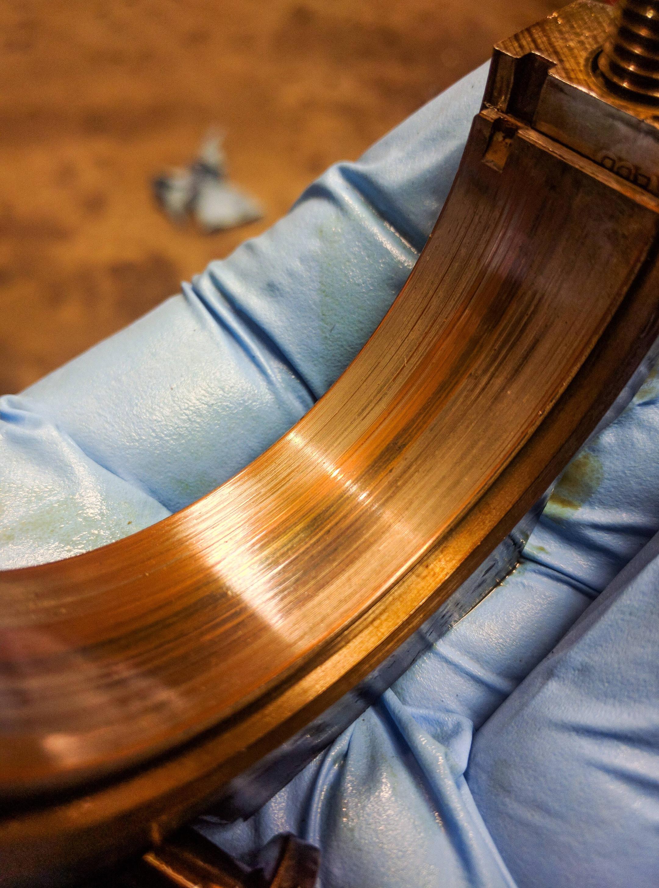
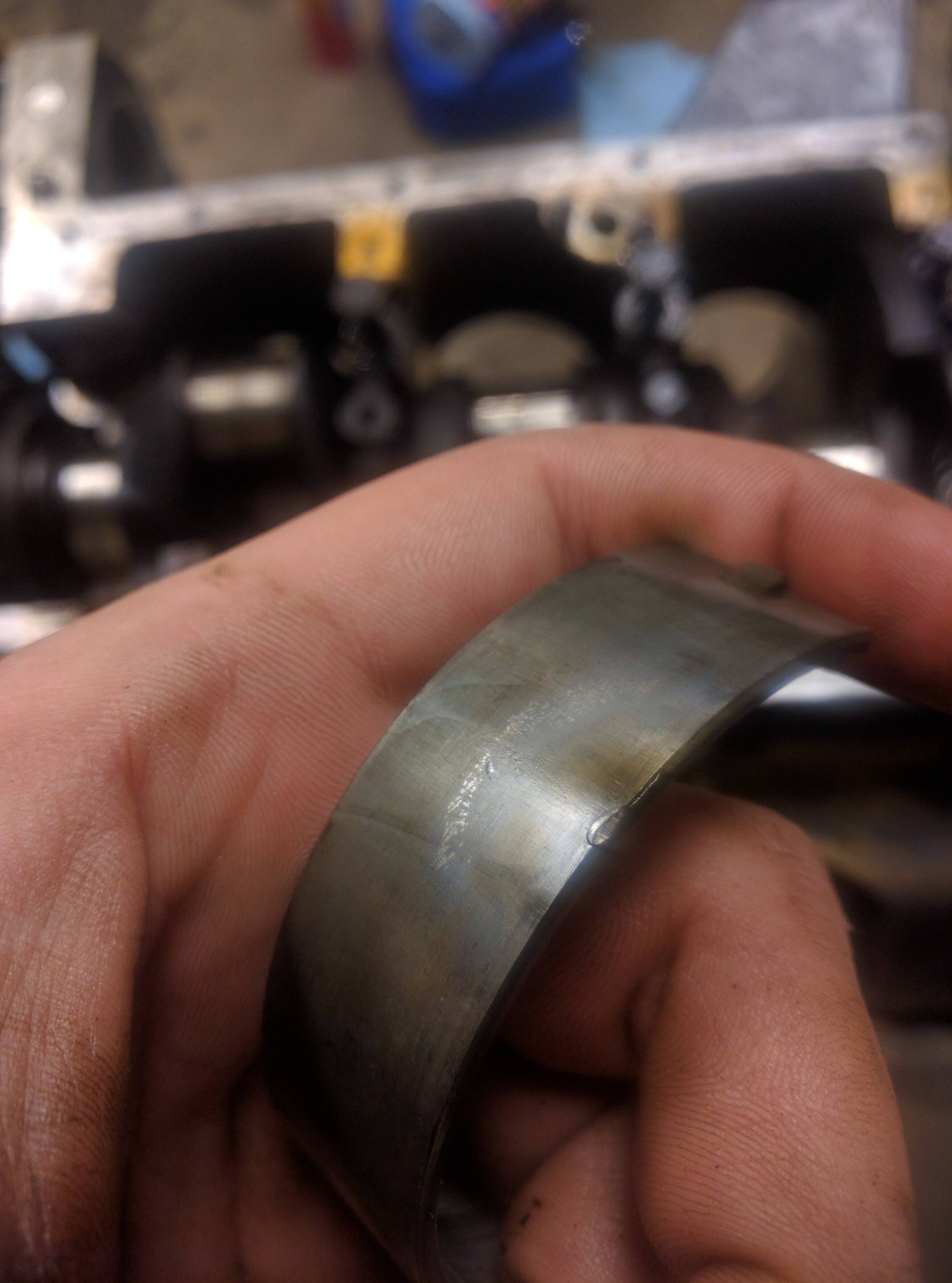
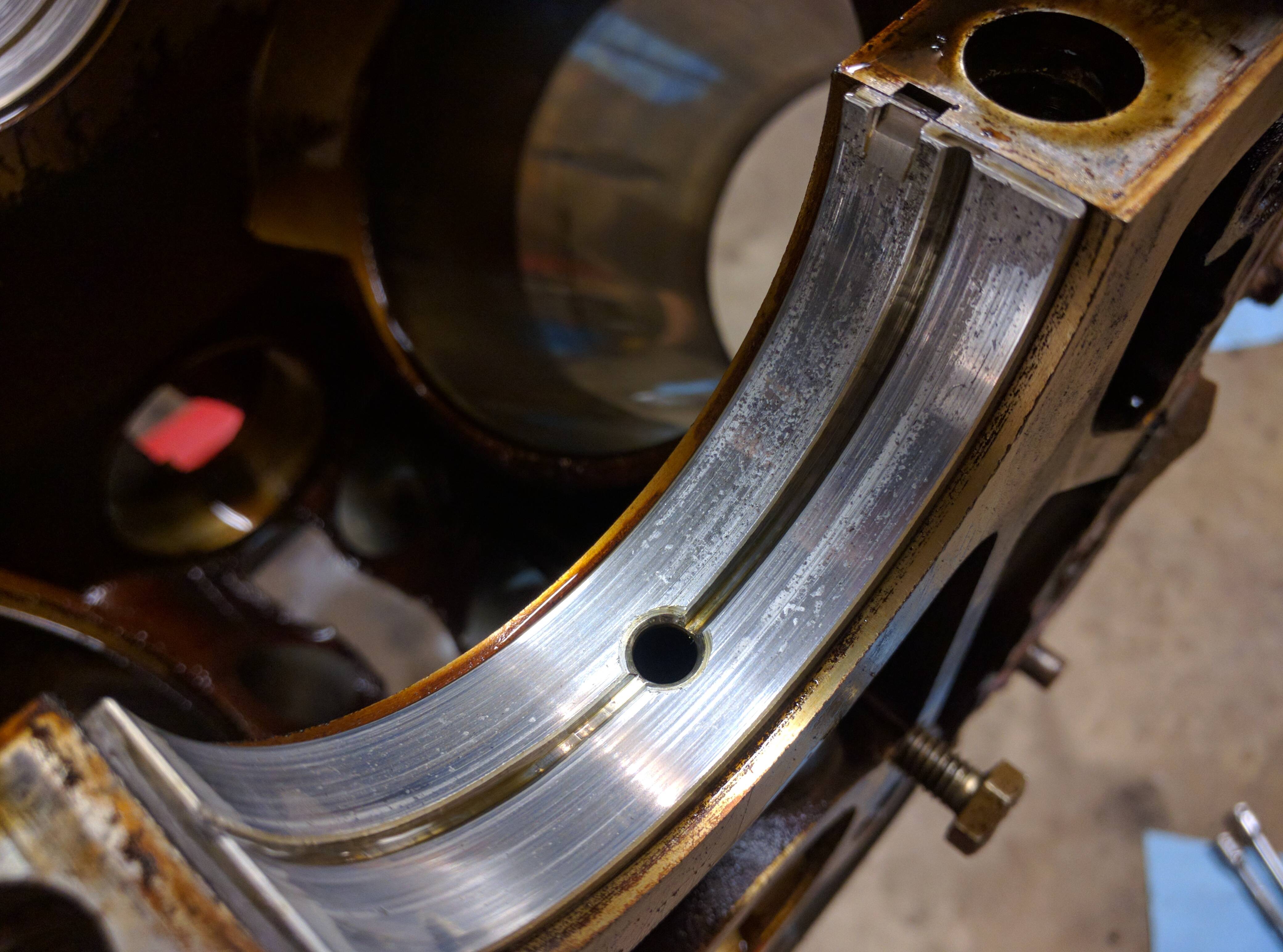
Here's the rear main bearing.
A closeup of the surface. Nasty.
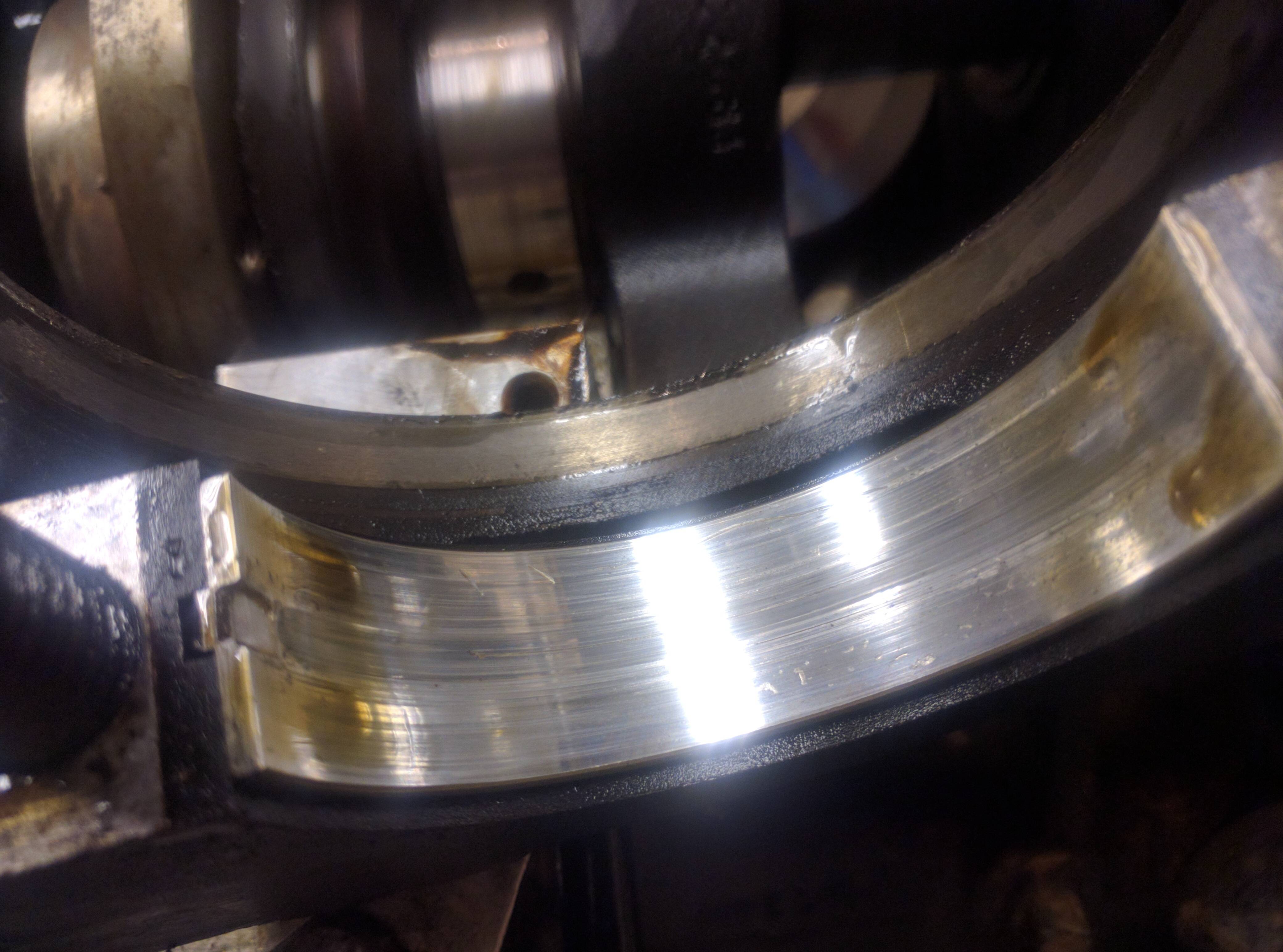
Here you can see the rear main seal. On a lot of motors this is a common leak area that is difficult to get to.
This bearing looks terrible in my opinion. It has a lot of pitting as well as scoring. The one score wanders a bit, which worries me.
This bearing also had a weird dent in the back. No clue what caused that.
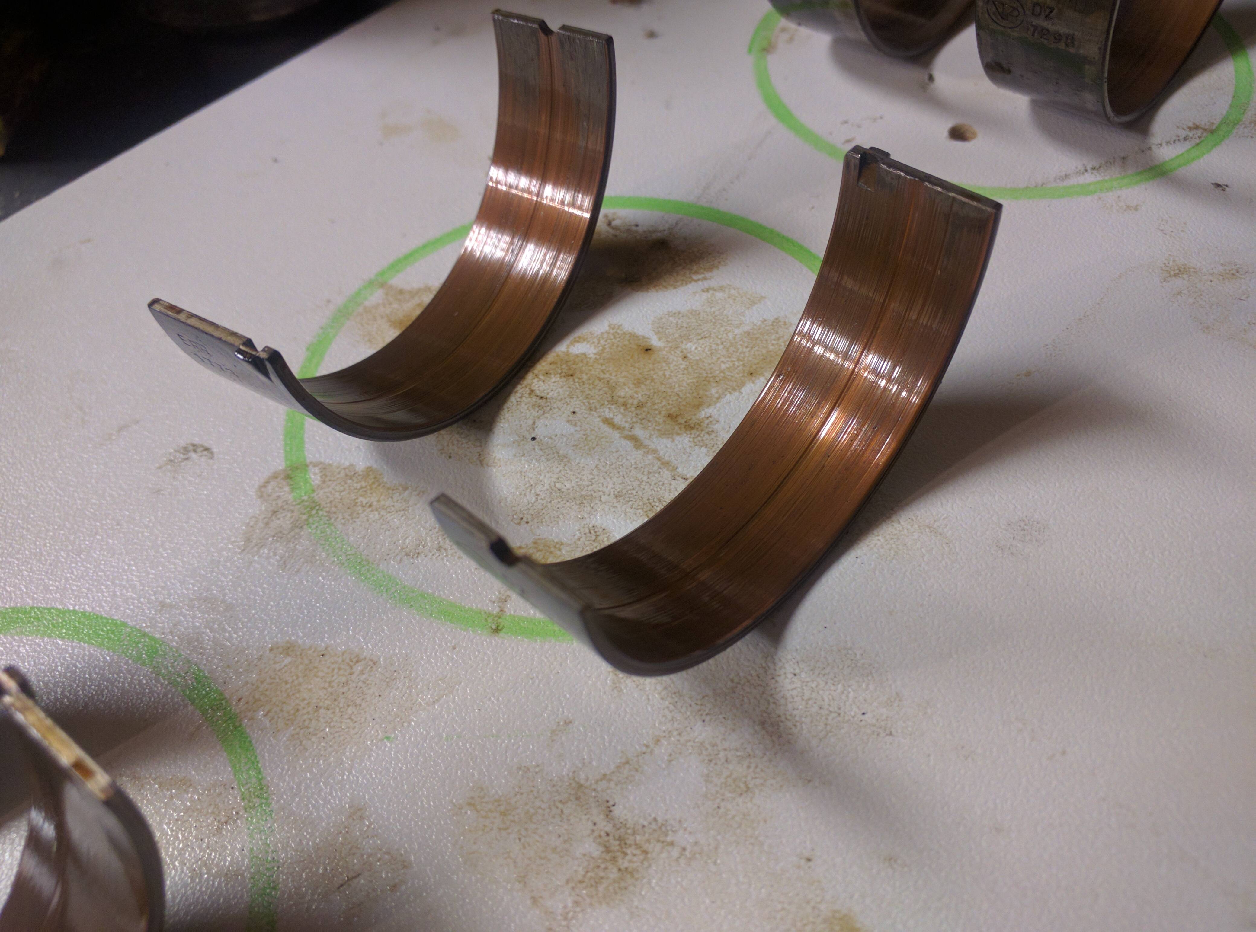
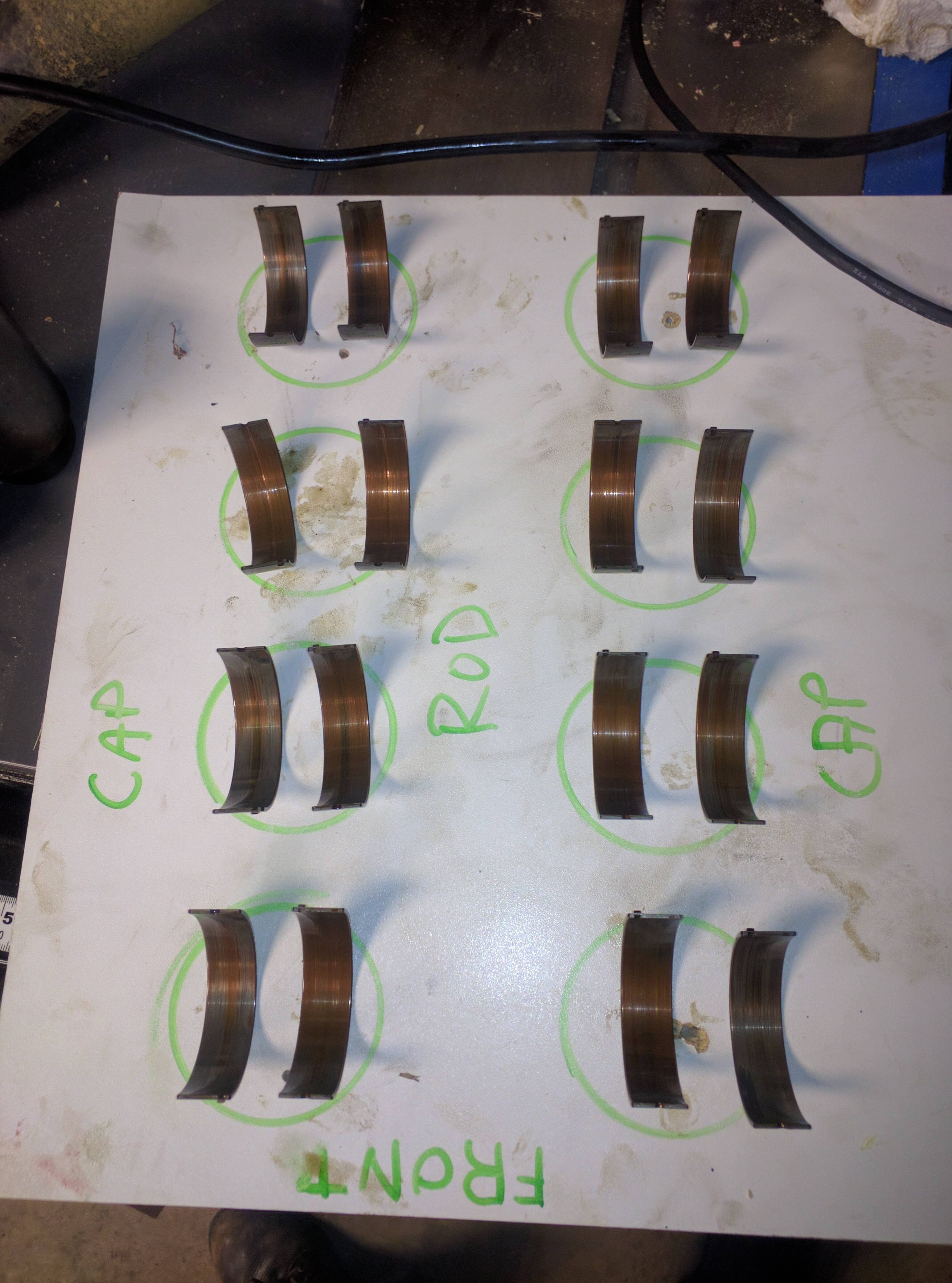
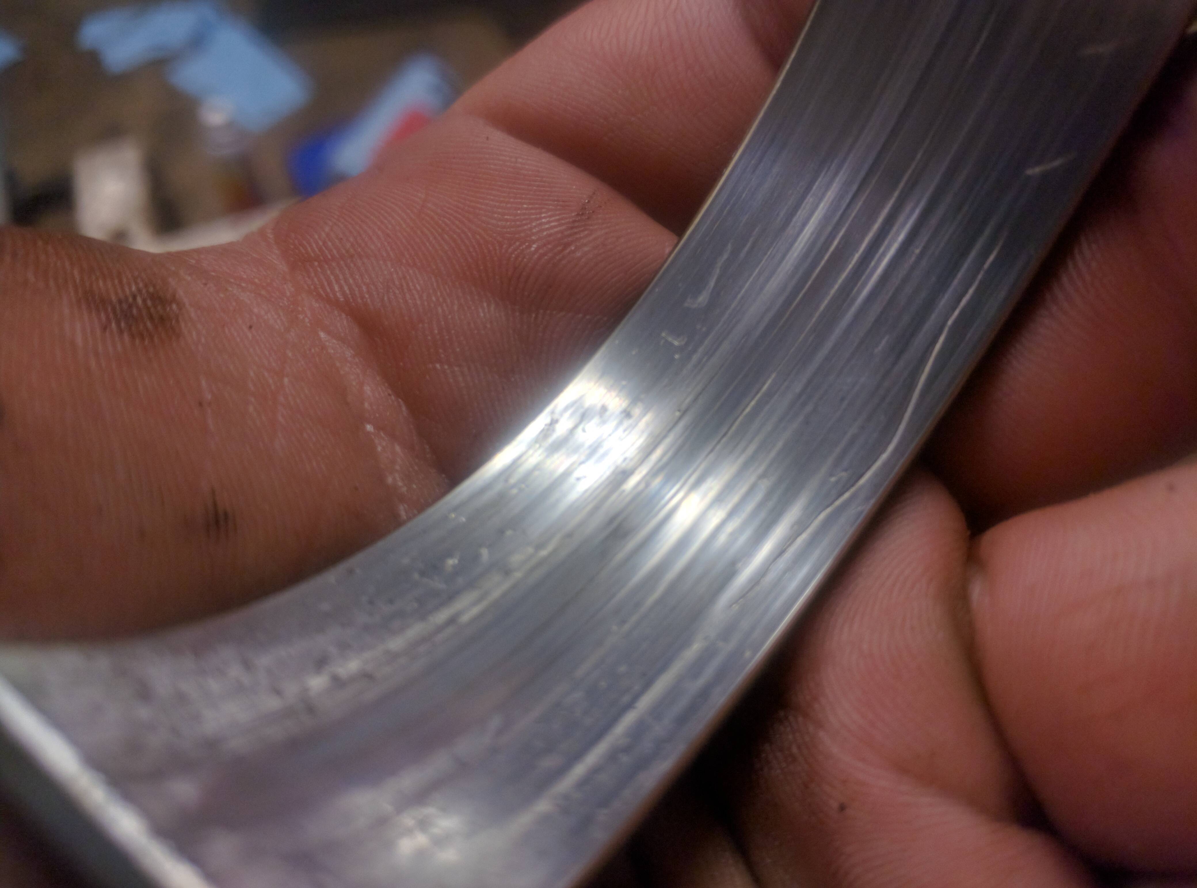
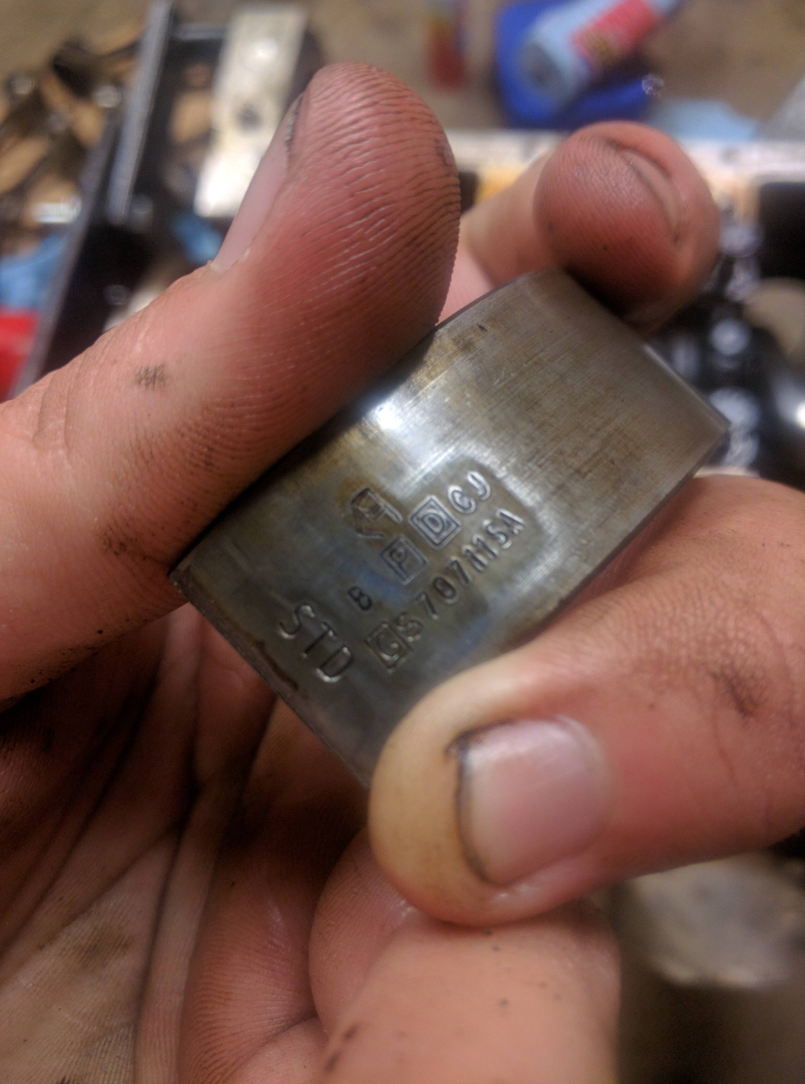
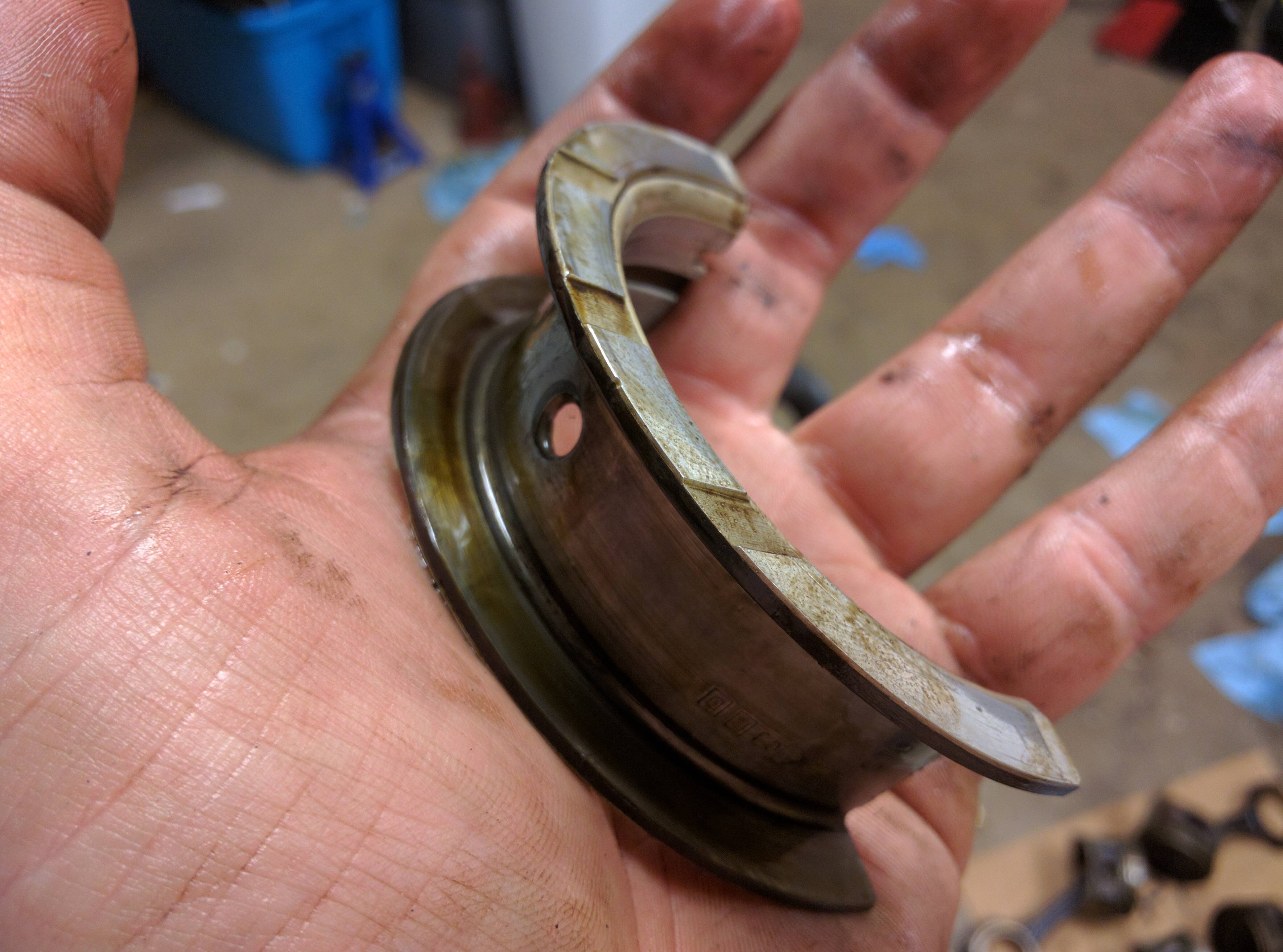
Here's the markings on the bearing. Can anyone tell me if these are factory bearings? You can see that the crankshaft hasn't been turned as these are standard size bearings, designated by the STD.
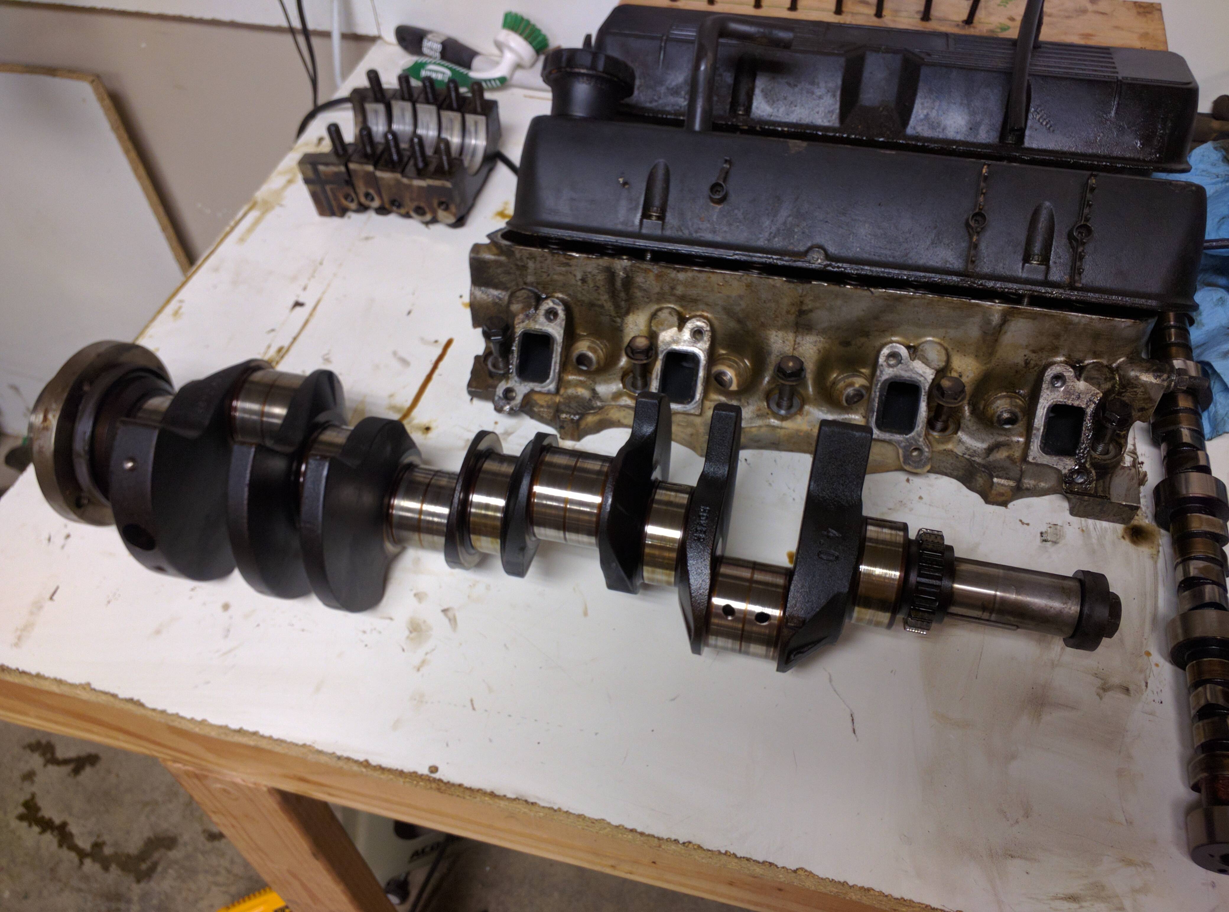
Here's all five lined up.
When you take the crankshaft out, make sure you have a flat area to put it down on. Also, they are quite heavy... be prepared for that!
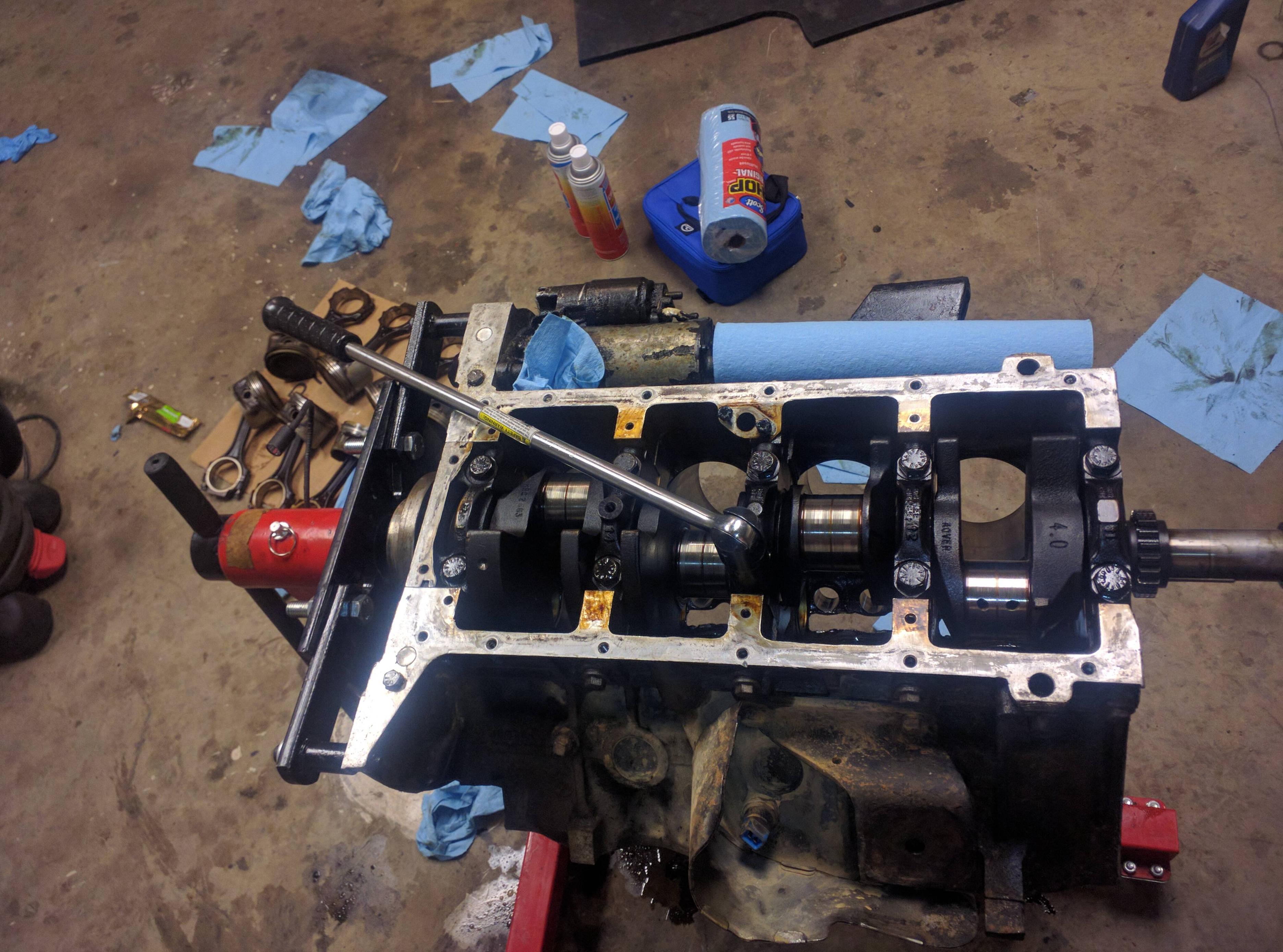
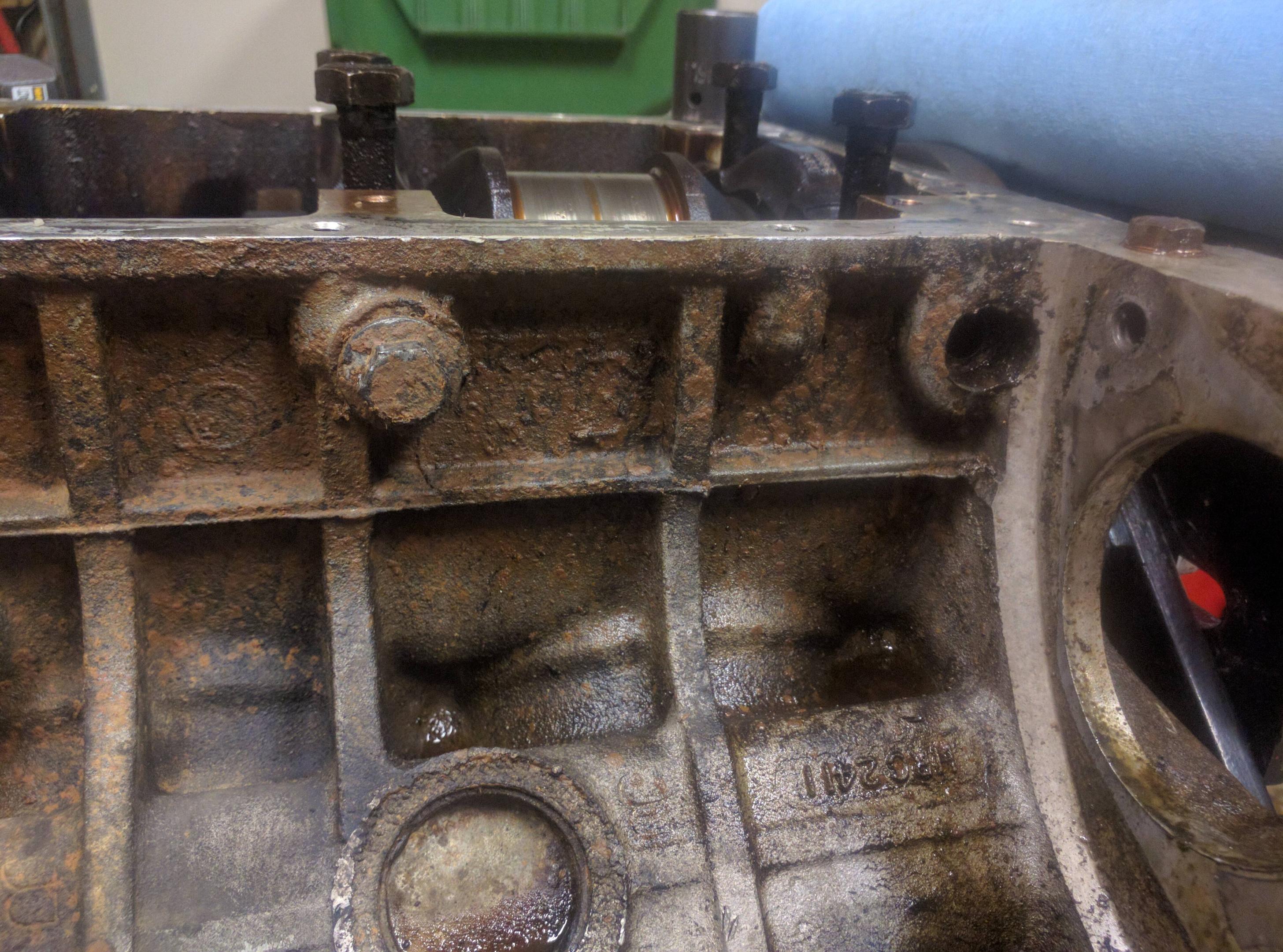
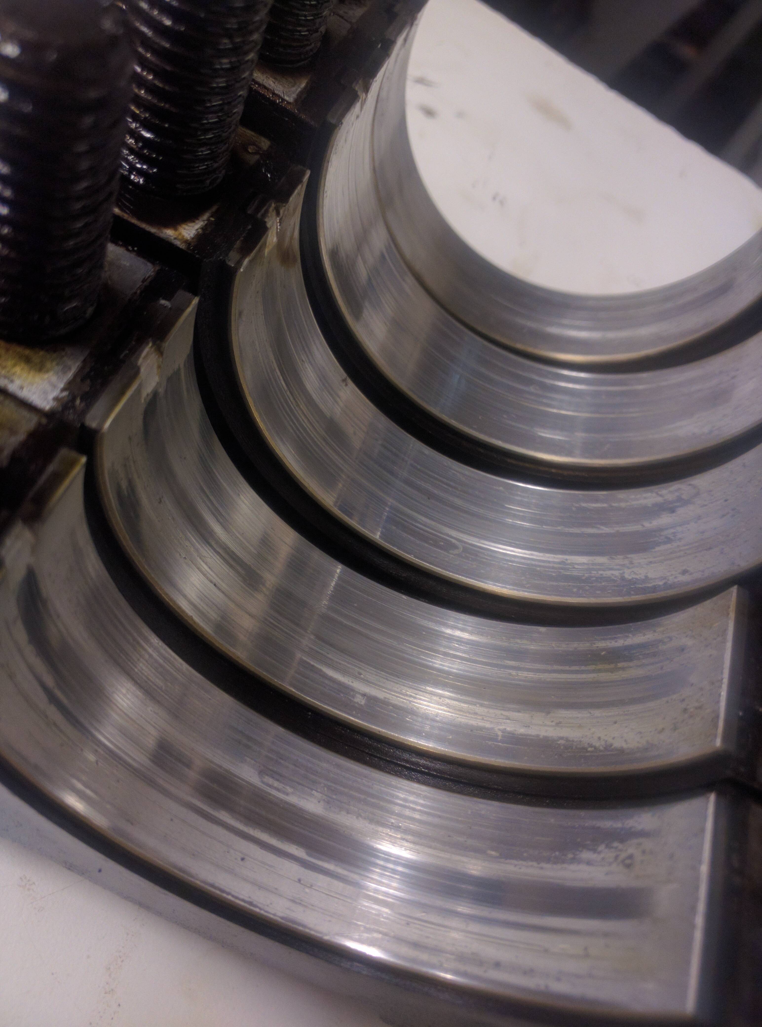
Here's the block almost totally stripped down. Top half of the main bearings still in.
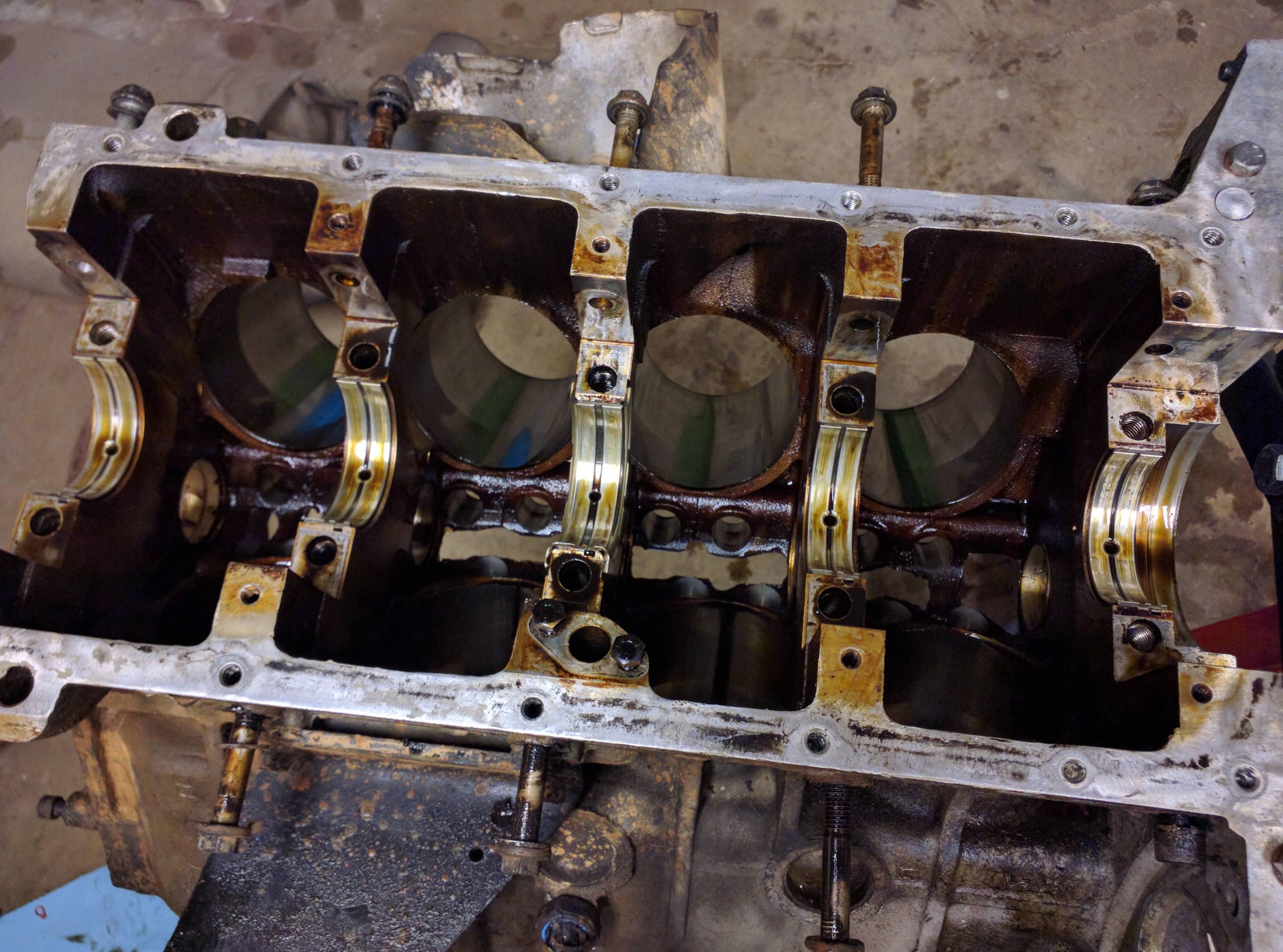
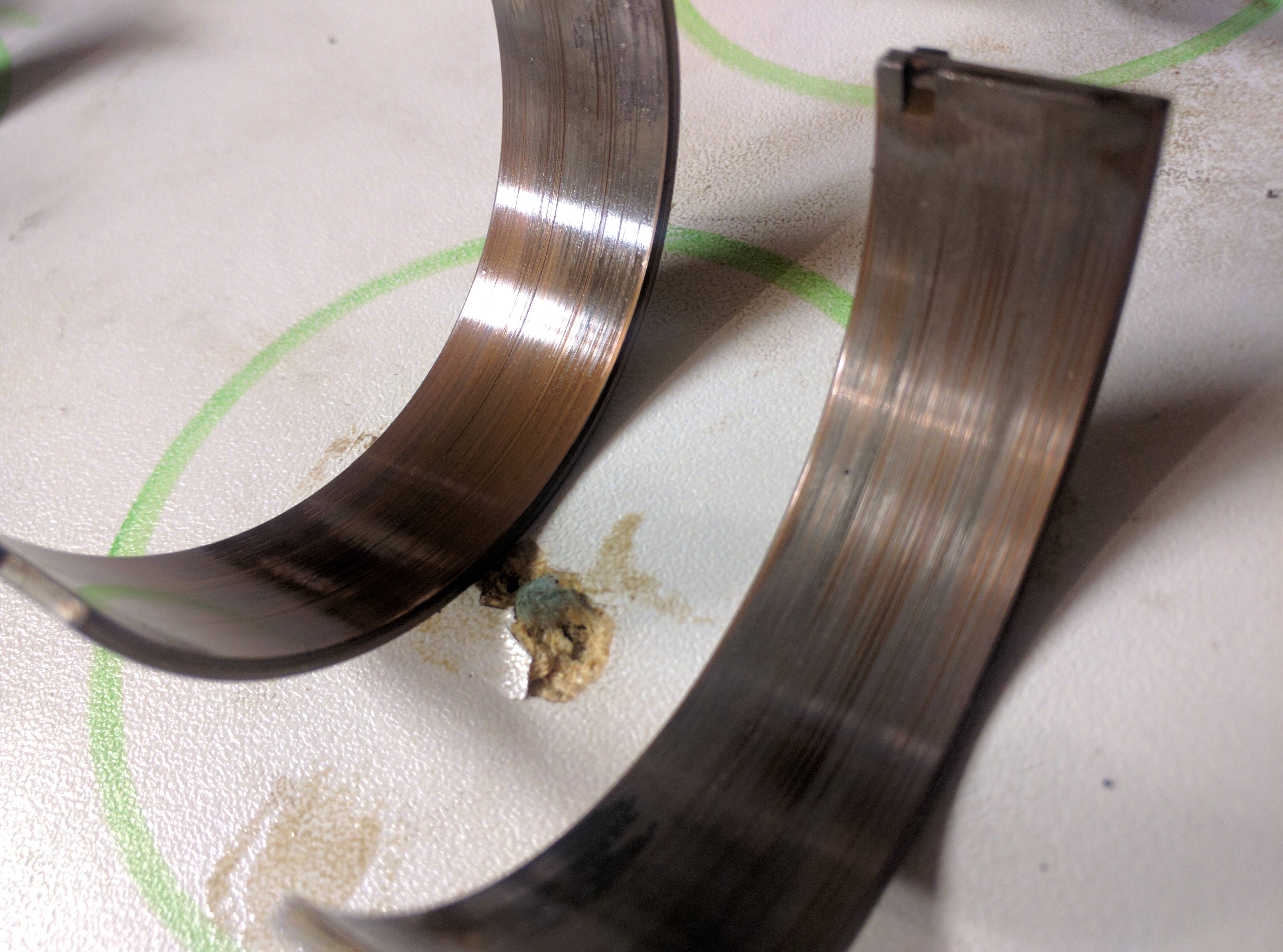
Not sure what caused this pitting, but I don't like it!
The center bearing is a thrust bearing, meaning it takes the load forward and backward axis load. Mine was pretty difficult to remove so I gave it a few soft taps with a soft rubber mallet until it popped loose.
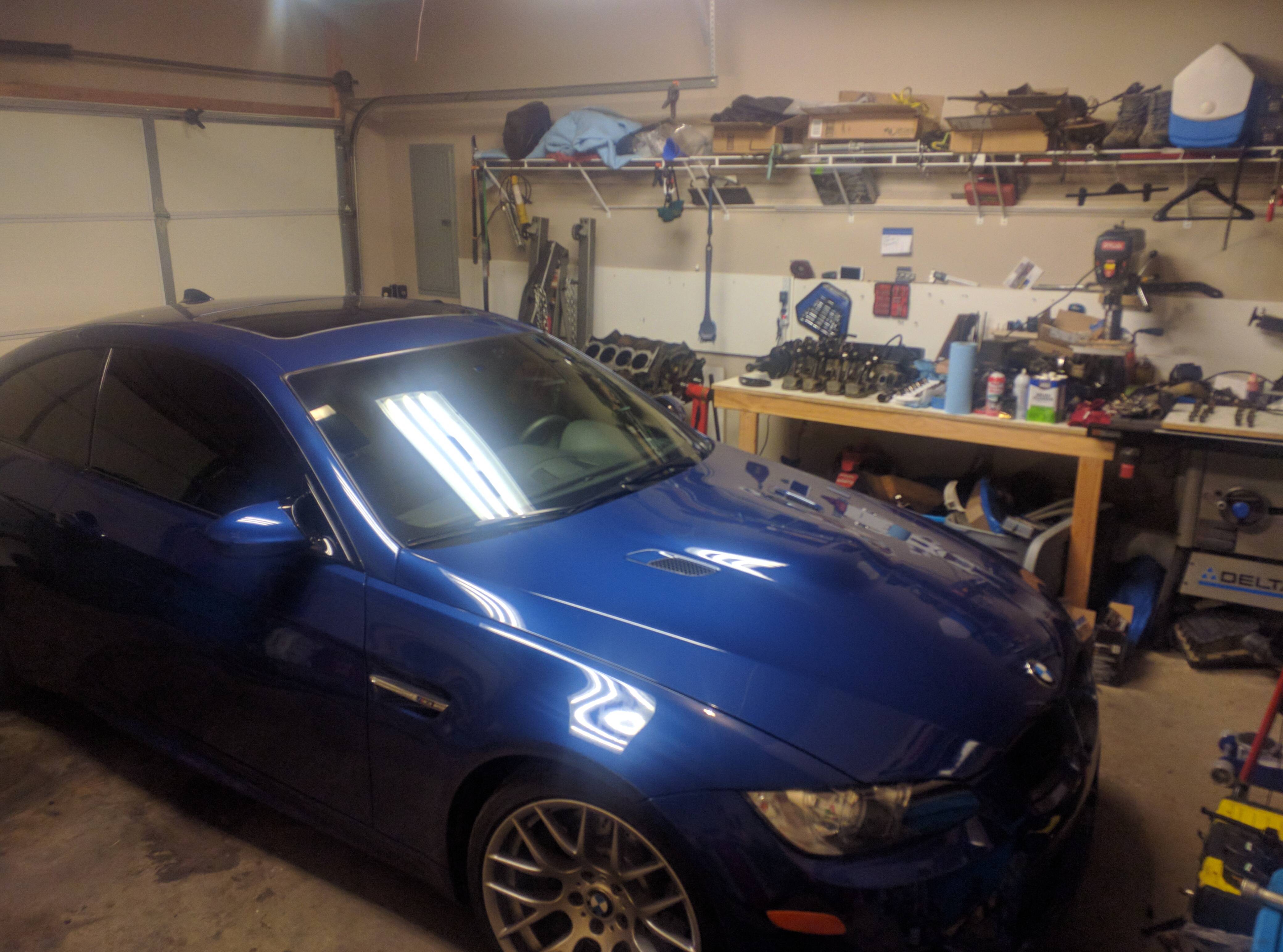
I took the rest of the time cleaning, everything as well as I could. I used a lot of carb and brake cleaner on the sides of the block to knock off a lot of the oil and dirt that's embedded into the metal. Most of the parts of my motor, externally, were covered in a combination of every fluid in the Land Rover since it leaked so much. Once I got everything cleaned and put away, I was able to get my car back into the garage for the first time in like a month.
Degreasing and cleaning parts can get expensive if you are using brake cleaner and solvents in compressed cans. I found this awesome YouTuber "Jafromobile" that shows how to make a DIY parts washer using compressed air and Mineral Spirits. Luckily my local Harbor Freight has just the tool I need.
Here is a link to that DIY parts washer YouTube:
If you use anything that removes oil to clean the cylinder bores, immediately re-oil them or they will rust. The rest of the block is aluminum, but the bores are iron and they will rust almost instantly. A good tip here is to use automatic transmission fluid (ATF) as it has a lot of detergent in it and will help get gunk off the cylinder bores.
After I get done cleaning tonight I might go back into detail about the oil pump, depending on how much time I have available. So far total into the tear down I have 9 hours of work including breaks and goofing off a bit.
Starting at the center bearing, follow the same procedure for removing the head bolts. Center out, a little at a time. It helps to have an enormous breaker bar. I got my breaker bar from Autozone. These bolts are 19mm, if I remember correctly.
The bearing caps have to go back where they came from. Luckily someone was nice enough to cast in a number and the direction in which they face. Arrows always point to the front of the motor.
Here's the 2nd one...
The rear main bearing is shrouded a little bit by the casting. I couldn't get my big 1/2 inch drive short 19mm in there, so I had to use this 3/8 inch tall 19mm socket. Always use the shortest socket you can to make sure you don't round off the top of the bolt heads.
I had neglected to remove my starter, mainly because I can't find my 8mm. I have an 8mm 1/4 inch drive that I totally sheared the 1/4 inch to 3/8 inch adapter on. I ended up jamming a T55 in there and that worked, except for I totally destroyed what I am assuming is a knock sensor. Oops. ...Oh my, that's an expensive part. Don't be like me, remove the knock sensor first. Anyone got a used knock sensor laying around?
The rear main bearing side bolt next to the starter is also a 8mm. Pesky thing.
So there's a trick to getting these bearing caps out. Once you have loosened all of the bolts, take the two large bolts on the top and pull them out slightly until you can get a good grip on them. This will give you something to hold on to when you pull the cap off. If you can't get them to come out like this, take a soft rubber mallet and whack on the sides of the bolts some. Don't hit your finger like I did... several times.
Here's the rear main bearing.
A closeup of the surface. Nasty.
Here you can see the rear main seal. On a lot of motors this is a common leak area that is difficult to get to.
This bearing looks terrible in my opinion. It has a lot of pitting as well as scoring. The one score wanders a bit, which worries me.
This bearing also had a weird dent in the back. No clue what caused that.
Here's the markings on the bearing. Can anyone tell me if these are factory bearings? You can see that the crankshaft hasn't been turned as these are standard size bearings, designated by the STD.
Here's all five lined up.
When you take the crankshaft out, make sure you have a flat area to put it down on. Also, they are quite heavy... be prepared for that!
Here's the block almost totally stripped down. Top half of the main bearings still in.
Not sure what caused this pitting, but I don't like it!
The center bearing is a thrust bearing, meaning it takes the load forward and backward axis load. Mine was pretty difficult to remove so I gave it a few soft taps with a soft rubber mallet until it popped loose.
I took the rest of the time cleaning, everything as well as I could. I used a lot of carb and brake cleaner on the sides of the block to knock off a lot of the oil and dirt that's embedded into the metal. Most of the parts of my motor, externally, were covered in a combination of every fluid in the Land Rover since it leaked so much. Once I got everything cleaned and put away, I was able to get my car back into the garage for the first time in like a month.
Degreasing and cleaning parts can get expensive if you are using brake cleaner and solvents in compressed cans. I found this awesome YouTuber "Jafromobile" that shows how to make a DIY parts washer using compressed air and Mineral Spirits. Luckily my local Harbor Freight has just the tool I need.
Here is a link to that DIY parts washer YouTube:
If you use anything that removes oil to clean the cylinder bores, immediately re-oil them or they will rust. The rest of the block is aluminum, but the bores are iron and they will rust almost instantly. A good tip here is to use automatic transmission fluid (ATF) as it has a lot of detergent in it and will help get gunk off the cylinder bores.
After I get done cleaning tonight I might go back into detail about the oil pump, depending on how much time I have available. So far total into the tear down I have 9 hours of work including breaks and goofing off a bit.