When you click on links to various merchants on this site and make a purchase, this can result in this site earning a commission. Affiliate programs and affiliations include, but are not limited to, the eBay Partner Network.
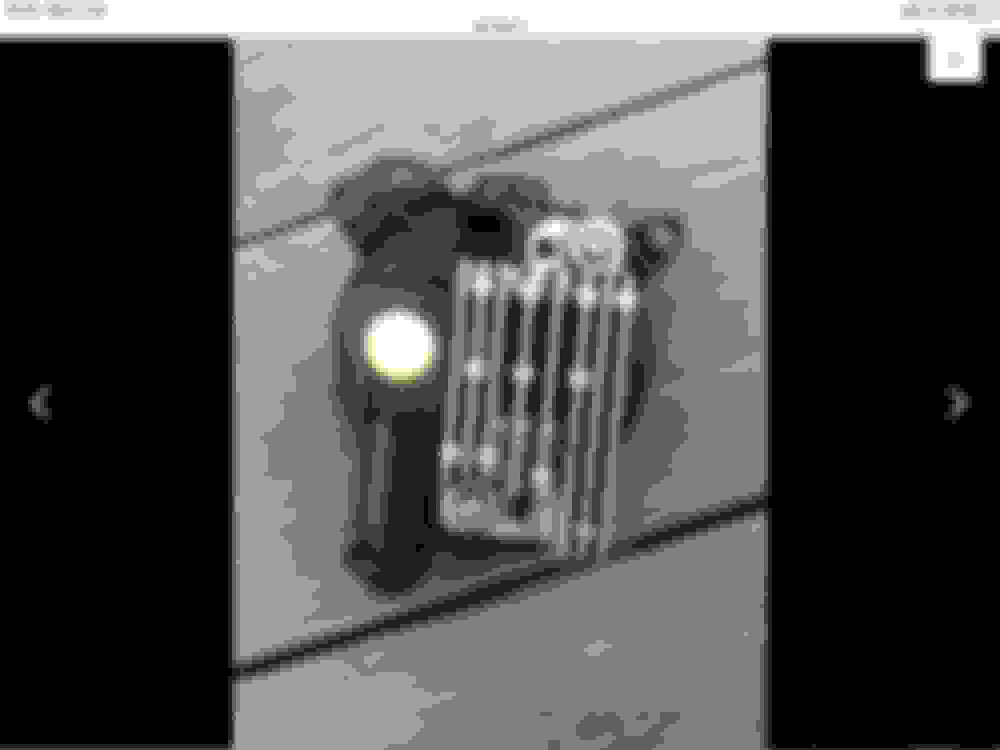
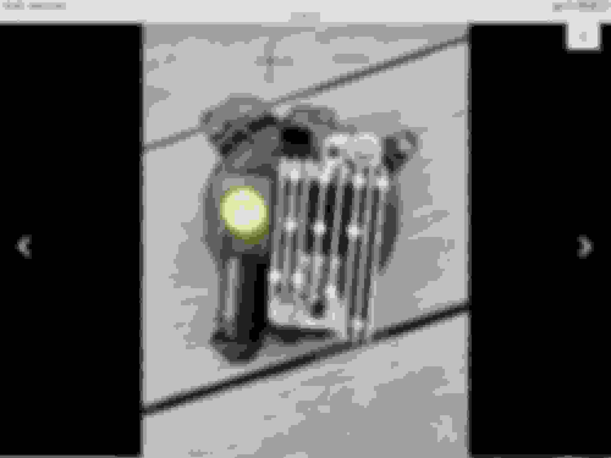
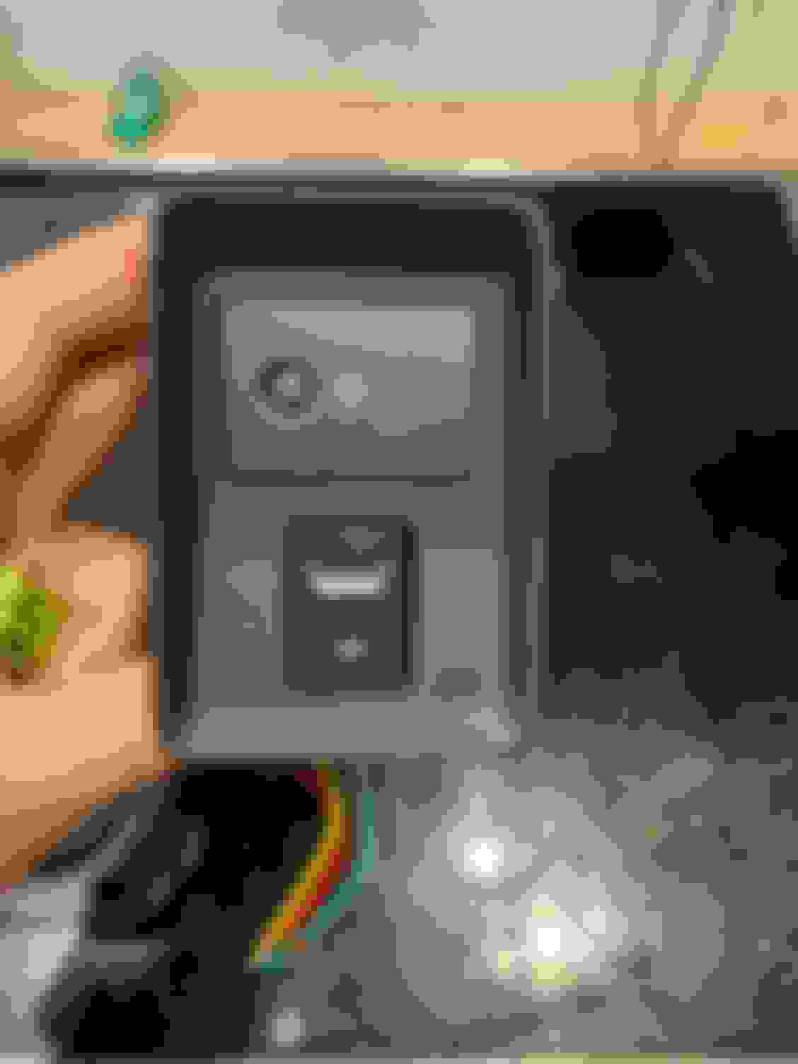
unfortunately after a lot of research I compared the photos of the main harness connectors,
the car without fog light does not even have the wires coming to the connector, I think in the photo there is a front bumper harness with fog light, two gray and one black.
you can clearly see a white cap in place of the gray wire.
everything becomes more complicated, you need the wiring diagram to understand the output pin from the combination switch and its path ....
I would just wire a separate dedicated fog lamps switch using the oem lights to make it look oem.
This is the solution. I was ordered mine without fog lights as I thought I could retrofit ones with an amber lens. SLBVO is on the money running a switch panel with your fog lights, light bar, and all your funny accessories.
Goodmorning everyone,
the work is continuing I ordered the various spare parts,
the wiring will not be the original one,
at this point a problem arises ...
the fog lights are Led, so you have to respect a positive and a negative sign, no trace on the connector, maybe a - is indicated, but I'm not sure.
can anyone please look at an electrical diagram?
Not sure what I'm looking at. Is that a JLR light or something else. It really doesn't matter though - get, use, borrow a multimeter and you should be able to check it. Here's a link that should help once you have one in hand. Google if you don't like this one (there's even lots of YouTube videos re: how to use the multimeter to test LED polarity).
If that's a JLR light (or someone else) try to get the connector from a parts catalog (if you don't have to buy the entire harness) or just wire it in directly yourself.
thank you very much,
I had seen the video,
but the doubt that it was not valid as in the fog light there is an electronic circuit such as voltage regulator and more.
curious that connected the fog lights and a power supply 12 v 3A, they do not work.
I finally connected to a car battery, and saw that in a sense of polarity it just doesn't work, but it doesn't break ...
Hello to all,
I have completed the installation work of the fog lamps.
I bought two plastic profiles for fog lights,
LR129434, LR129433,
2x YPC911650 fog lights connectors,
the wires with the plugs for these connectors: 418238.
1 wiring kit with 40A relay.
1 switch to adapt with white lighting.
to install the new headlights I did not have to remove the bumper, the headlights pass through the holes behind the front grilles, with a little effort I screwed in the torx screws that fix them.
instead for the wiring from the left headlight I had to remove the front grille, otherwise I could not bring the cable on the right near the positive pole of the battery.
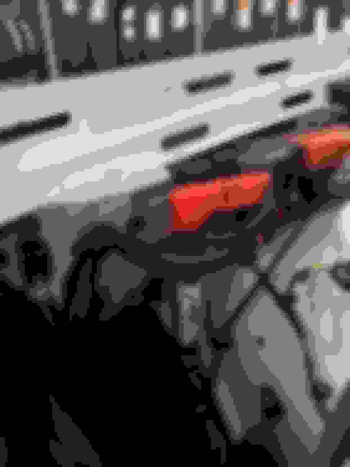
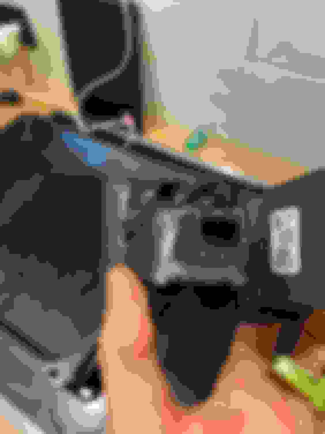
on the photo you can see the relay installed, following the instructions taken from the network, I passed the cable under the front cover and entered the passenger compartment from the large rubber cap of the steering column.
I had to adapt the new switch to the hole provided under the instrument lighting adjustment.
for the connections, main positive and negative from the sockets in the bonnet near the relay, for the control positive, at the suggestion of Turf63, whom I thank, I took a blue / white wire in the connector of the lights adjustment, initially in the brake connector electronic, but unplugging this connector generates an error ...
to finish I worked, the hole cover cap and I glued the new switch inside.
Well done! I know you've been searching how to get it together & source parts. Love hearing the successful stories of mod'ing when people want to get their Defenders to the specs they wanted. Only wish it weren't as hard. But then again, you're never proud of anything that comes easy!
Now you need to install ClearView after the manufacture so you can tell everyone how that worked for you!
hello GrouseK9,
how do you know this?
I was just thinking about it .....
the biggest problem is that the diagnosis is needed to activate the function .... I'm waiting for the updated Gap tool to defender in order to activate the various functions.