
Stock switch wiring advice


Thread Starter
|
Camel Trophy
Joined: Nov 2009
Posts: 4,079
Likes: 227
From: IL
I want to use the Volume Up/Down buttons for my Winch In/Out controls inside the cab.
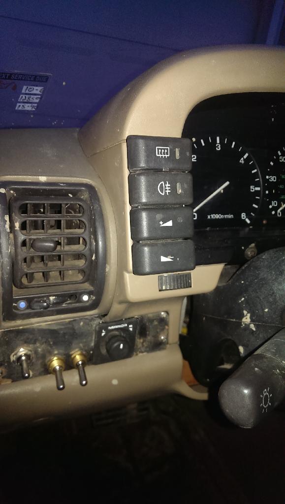
I'm having issues determining the pin-out for the stock switches though.
I thought one would be power in, one power out to the radio, one power in for the illumination, and a ground. That's not what I'm finding.
Here's what I have for pin-out:
1-BRWN/YLW - 4.18v with key on
2-RED- 8.84v with headlights on
4-BLK- no voltage
5-BLK- no voltage
So I need a little help here. Here's the wiring diagram from the RAVE.
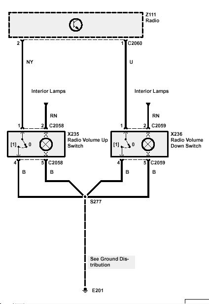
I want to have 12V coming in and 12V going out to the winch solenoid.
Any help on what pins I need to use or what the heck is with that diagram????
I hate electrical, FYI!!
Baja
Joined: Mar 2009
Posts: 5,736
Likes: 230
From: south n.j. and ne va.
Pin 1 NY
Pin 1 U
Whatever color those are. They are what you want and that's an awesome idea but they complete a ground circuit, or short the radio to ground, to use you need to cut pin 1 to run out to the winch and pin 4 to attach to 12 volt
P2 is power in for lights RN
Pins 4-5 are grounds guessing B. Is black
Where is 3?
Not sure it will work but worth a try since it is just turning on the solonoid not carrying current
Last edited by TOM R; Jan 13, 2014 at 05:42 PM.

Camel Trophy
Joined: Jan 2010
Posts: 4,245
Likes: 402
From: Traverse City MI
What winch and do you have a control box for inside the cab or remote outside the truck?
This is what you want/have currently.
NU = Brown/Yellow at pin 1 +12V (up) winch line in tied to winch in-cab control.
U = Blue at pin 1 +12V (down) winch line out tied to winch in-cab control.
RN = Red/Brown at pin 2 would leave as they are your switch backlighting.
B = Black at pin 5 are grounds for switch backlighting.
B = Black at pin 4 on both up/down are switch grounds that you'd hook up to the winch's in cab remote.
Last edited by ihscouts; Jan 13, 2014 at 06:28 PM.
Thread Starter
|
Camel Trophy
Joined: Nov 2009
Posts: 4,079
Likes: 227
From: IL
I have the Viking GS-9 winch. The Albright solenoid is remotely mounted behind the grill. The winch remote plug is remotely mounted on the grill just above my Hella light.
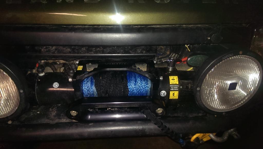
There's no in-cab control for the winch. That's what the Volume Up/Down buttons are going to be for. The 12v out from the switches will go back to the solenoid.

There's no in-cab control for the winch. That's what the Volume Up/Down buttons are going to be for. The 12v out from the switches will go back to the solenoid.

Mudding
Joined: May 2013
Posts: 243
Likes: 5
From: NE CT
1 & 4 on each switch will give you a set of normally open contacts. However, those switches are signal level only and are meant to ground a very low current signal pin going into the radio microprocessor to signal to the radio micro that the volume was adjusted by a click, and then the adjustment is made via software. They are probably not meant to carry any current whatsoever, I would recommend figuring out how much current your solenoids will be drawing by measuring the resistance and I=V/R and if it's more than a few milliamps, install interposing relays. Some of those solenoids can suck down a fair amount of current when they engage.

Thread Starter
|
Camel Trophy
Joined: Nov 2009
Posts: 4,079
Likes: 227
From: IL
Question though. Why does the winch controller not need relays? Bigger wiring, higher rated switch??
Baja
Joined: Mar 2009
Posts: 5,736
Likes: 230
From: south n.j. and ne va.
The controller is only to turn on the solenoid, that carries all the current, the solenoid is just a big *** heavy duty relay
Volume switches are not made for current but I say worth a shot worst happens you burn the switch up or like scouts says wire relay inline
Volume switches are not made for current but I say worth a shot worst happens you burn the switch up or like scouts says wire relay inline