

Knock sensor questions (driver's side)


Thread Starter
|
Drifting
Joined: May 2015
Posts: 31
Likes: 0
2003 Disco II 158,000 Miles
This might be pretty confusing and I may have to post pictures.
I'm getting a pending code P0327 which is a low input on the knock sensor.
I went underneath there to check it out and clean the connectors and I found a redneck splice.
So the pigtail connecter has a red and a black wire. the red wire haflway up has a black coating under it, directly under the black wire is a copper braided wire, under that is the red wire.
The black wire is spliced into the copper braiding and then they have put both, the braided wire connected to the black wire on the pigtail plug connector and the red wire into the butt connector spliced into one whit wire that I am assuming goes to to the ecu.
Now the confusing part for me is that the red wire was not stripped and isn't really connected to anything. But, is in the splice along with the braided copper connected to the black wire on the pigtail.
How the hell is this thing supposed to be wired? The way they have it splice is obviously wrong and I need to know how to actually splice it together to get rid of the low input code.

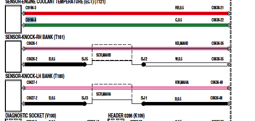
According to the schematic, the red(positive +) wire is inside the shrouded black(negative-) wire. So yours may be correct if the negative wire is in fact connected to the shroud. Also it shows the negative wire going to the white wire that goes to the ecm. This is for the right bank.
on the left bank the black wire is black all the way to the ecm.
on the left bank the black wire is black all the way to the ecm.
Last edited by Joemamma1954; Jun 8, 2015 at 06:51 PM.
Thread Starter
|
Drifting
Joined: May 2015
Posts: 31
Likes: 0
So are you saying that both the shroud, which is connected to the black wire, and the red wire should both be in the butt connector that splices into the white wire? Because it's like that right now but the red wire isn't stripped allowing a connection, It's jsut sitting in the connector but not bare it still has the coating on the red wire. so the only one thats giving a signal of any sort is the blac. Should I strip the red wire and shove both into the butt connector?
No, the red wire goes to the ecm separately from the black wire which connects to the white wire, which in turn goes to ecm.

Thread
Thread Starter
Forum
Replies
Last Post