When you click on links to various merchants on this site and make a purchase, this can result in this site earning a commission. Affiliate programs and affiliations include, but are not limited to, the eBay Partner Network.
As mentioned one issue is screen brightness, it is constantly on full or near full brightness when running. Sure, there is a screen off button on almost every info display. But if you want to use it at night you are nearly blinded. So after exhausting a way to make it work internally, via a jumper or solder bridge, I ended up taking direct control of the backlight LED light strip with an Arduino device. It drives the backlight directly using PWM and its independent of any other illumination input. LED power is still pulled from the same source as the Nav unit, so no change there.
I placed the photocell in the center speaker cover with a nice Fresnel lens. Helped create a nice clean look. The Arduino module I created sites to the right of the display and down in a hole in the dash. I still have access to its USB port for additional programing adjustments.
I have some things I need to polish in programing to make it smooth out a little, but for now it works and its nice to not have a crazy bright display at night.
Would this work on a 2010 lr4 base with tiny display
I have a 2010 lr4 base with the tiny display but today I was able to buy a 2010 lr4 hse navigation display, radio unit with clock and the dash cd. I took apart the dash and although all the parts physically fit perfectly, the connectors do not. Is there any way of making it work?
After starting my 2005 LR3 and driving for approximately 25 minutes I�m getting a suspension fault on the dash of course it resets with the key being removed after the car is turned off, I�ve noticed no dip on any of the corners of the suspension. Trying to figure out if I should replace the compressor the solenoid or just buy the whole suspension kit and replace all the shocks. Is anybody else had this issue and if so how did you rectify it. TIA!
You should post in the appropriate forum, this about upgrading the screen.
I need to find which laptop its on, then I can post it here. I have fine-tuned it a little and it works very well but its not as smooth as I would like. But it works and its not bothersome. Certainly 100X better than having an always bright display. I will post when I get a chance, hopefully soon. If I don't, PM me to remind me! As for shematics, I don't have any for the setup but I can provide some pics and a list of what I used. If one has some basic soldering skills, its not hard to build.
A BOM would certainly be useful. I think, based on preliminary investigation, that any of the 42 (…) Arduino boards in existence would work. Based on your description one needs a DIO pin (in) for the light sensor and another DIO pin (out) configured for PWM and I guess frequency. I’m reasonably sure I can figure it out based on pictures, seeing the source code and knowing what board you originally wrote it for (for the pin out diagram/mapping). I noticed some Arduinos support micropython nowadays, the libraries seemed to support both GPIO and PWM, like the Nano 33 BLE (and RP2040 Connect and Nano 33 BLE Sense).
The case that you used seems to imply an Uno/Zero board.
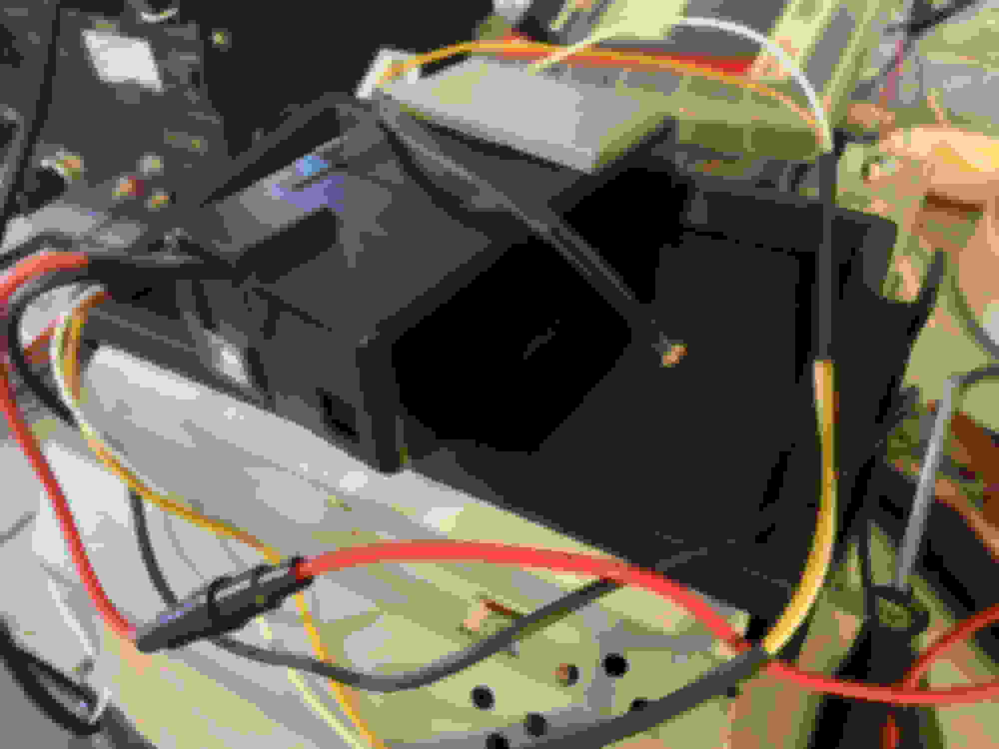
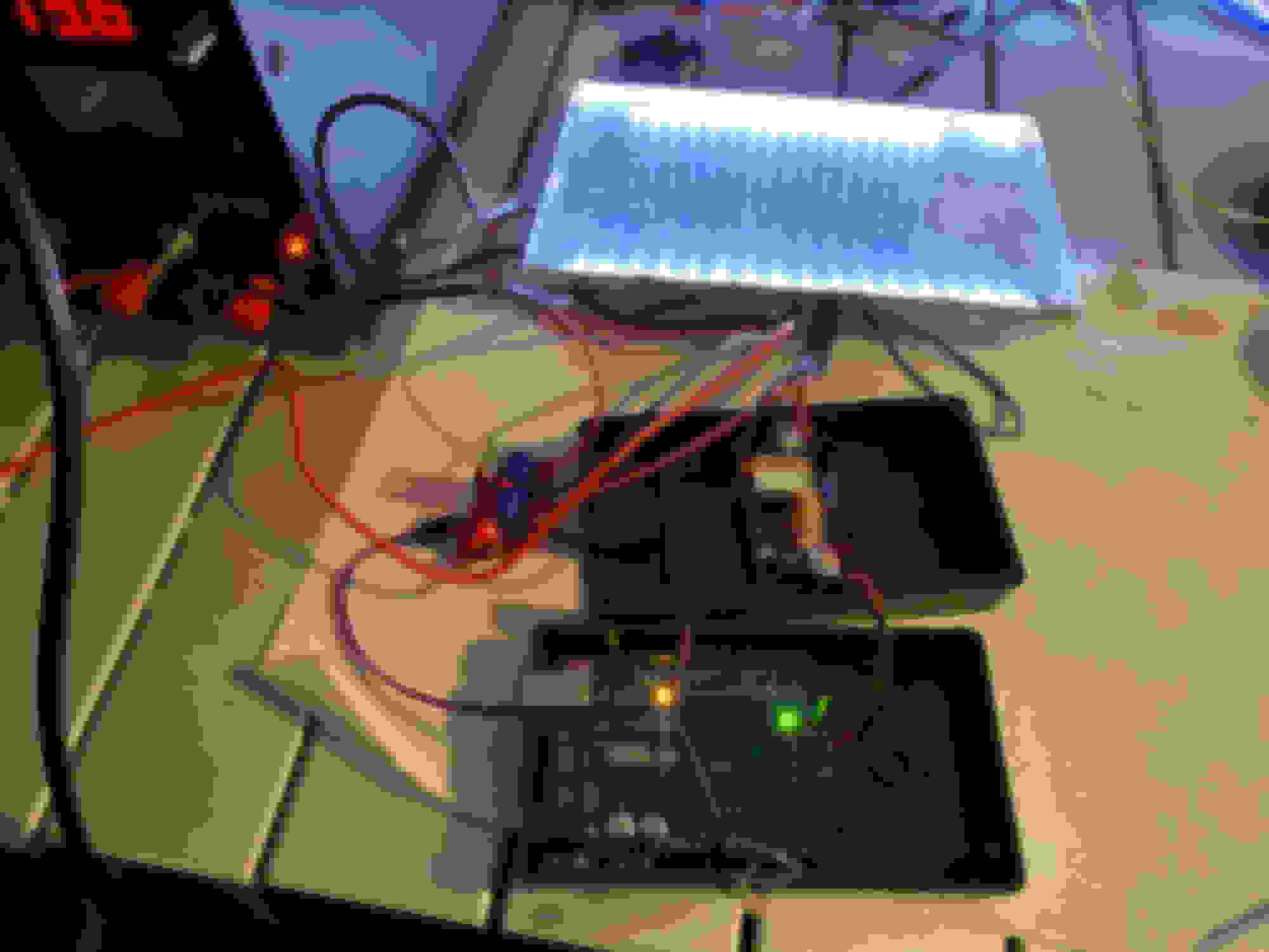
Lighting module. I had to use three components to drive the backlighting. This is because the Arduino itself can't handle the load or even output the correct voltage actually. Here are the parts I used:
Okay, from memory the reason for this setup was as follows. The Arduino operates at 5VDC optimally. While they can get pushed to 12v, the trucks operating voltage of 14v would likely damage it, if not right away in short time. So the DC-DC buck drops voltage down to a nice steady 5VDC. Since vehicle voltage fluctuates, this is actually just nice to have anyway to keep the Arduino happy. The other issue though is the Arduino output, since its only taking in 5V it can not output more than that over PWM. That will not be enough for the display to reach full brightness. So the mosfet takes two inputs, vehicle 12VDC and the PWM output from the Arduino and thus "amplifies" the PWM signal at 0 to 14v or whatever the trucks VDC is at the time. I have been operating like this for some time now with no issues at all.
As for the programing, I have several laptops and I am looking for where it is. If all else fails I will read the module and DL it.