When you click on links to various merchants on this site and make a purchase, this can result in this site earning a commission. Affiliate programs and affiliations include, but are not limited to, the eBay Partner Network.
LR3 to LR4 Navigation Display / Touch Screen Upgrade
Version 1.0.1 = 11/28/2020
This thread will cover the install and answer questions on swapping in a navigation/touch display from a Land Rover Discovery 4 into a Discovery 3. I will also have two other threads going over Bluetooth upgrades and iPod integration. I tend interchange LR3 and LR4 with D3 and D4 often, FYI. The vehicle this was done in was a 2006 LR3 North American market.
Other related threads to be posted here: Bluetooth phone module upgrade: https://landroverforums.com/forum/lr...upgrade-99024/ iPod integration (portable audio module from an LR4/give you on-screen music navigation) Backup Camera
This forum and myself make no claims that this project will work in every vehicle and we are not responsible for any damages that could occur from making this modification.
Background:
This project must give credit to Flack on the UK Disco 3 forums. He had the original idea and did much of the initial footwork. Many others contributed too! This was an inspirational project and for myself well worth the upgrade! I often travel with no cell coverage and need proper navigation. The original thread is, at this time, 41 pages long and while there is much redundancy its overall worth the read: https://www.disco3.co.uk/forum/d4-sa...d3-120453.html
The concept is simple, install a D4 display into a D3. You can not install this if your Discovery lacks the MOST fiber optic network, no exception. If you lack a 6-disc CD changer then odds are you do not have the MOST network. In theory one does not need an existing display to install a D4 display and I will be attempting this with my neighbors Rover. While he has the MOST network there is just a storage cubby where the screen would be.
There will be some fab work required to fit the display, actually demolition might be the better term. A basic Dremel will come in very handy for cutting plastic and metal. You will also have to run cables from the MMM (Navigation DVD module under drive seat) through the center console up to the new display. If no display was originally fitted you will instead have to locate and run a wire from the ABS unit for vehicle speed signal. If this wire is not fitted the navigation part of the system will fail to function properly even with an acquired GPS signal. And if you had no navigation, you will need a GPS antenna - a solution has not been devised yet. Assumption is that one will need to install a GPS antenna, OEM or otherwise. Solution and fitment would be up to you (maybe tuck the GPS in the center speak if speaker is not installed?)
Familiarize yourself with what the MOST network is and how it works before stating this project.
There is one issue that is still being worked on, backlight illumination seems to now be carried over the MOST network versus the CAN bus. The original D3 display does have illumination input (red wire) and the D4 screen does have illumination input identified. But D4 diagrams show no wire connected at input. And since the D4 nav display does not use the CAN bus there is no alternative source for determining illumination. I am digging further into this myself and will update here. There is a good chance a simple external potentiometer could be installed to adjust brightness including one with a photocell. This would probably require modification of the display itself. Also it may be that the D3 uses both the wired input and a CAN bus signal for illumination, cause things can never be truly simple on a Rover. Luckily the D4 display has an off button shown on nearly every screen.
After dissecting a nav unit I could find not physically find a way to switch the method for backlight regulation. It seems they displays may have been designed from the start to have a data signal determine illumination levels even though wiring diagrams indicate an illumination pin.
Once the display is fitted its no longer possible to update the maps. If you want the latest update the donor vehicle should have an update done before removal. This is a dealer only service and is VIN locked. It is NOT possible to swap hard drives from another unit to get more up-to-date maps.
What is needed:
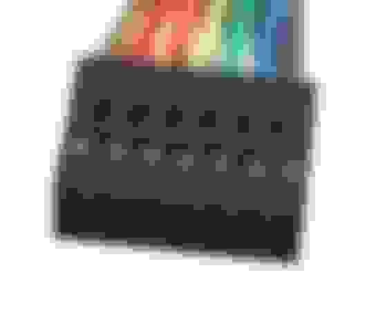
• Navigation display from a 2010-2011 D4. Other Range Rover or Sport displays may work fine, I will not cover those here. Up to 2010 the Navigation display in the D4 consisted of two parts. The MMM and the display. Come 2010 the display became a single integrated unit containing a hard drive which stores all the map data and the GPS receiver itself. Starting in 2012 the system became two parts again. So for this upgrade to work, you must purchase the correct display. I highly recommend you source a display from your region. So if you are in the US dont buy a UK display. The proper display is easy to identify. US displays will say ROW on the back while Euro displays saying EU. I dont think the actual part number matters as long as it looks like below. EU models have an extra antenna white connector above the blue FAKRA connector found on all versions. That extra antenna is for radio based traffic information, something we do not have in the US. You will need a FAKRA splitter cable if using this feature and may need an additional traffic module. If you did not have an existing display installed, you will need either a bottom mountain plate from a D3 or have to get creative with some metal works. *** NOTE: Its been discovered that some units may not have reverse camera ability via direct wiring. I have three D4 Nav units, all the same hardware and software versions. Yet one does not work with the reversing camera feature. To date its not known why and others on the Disco forum have has the same issue, including Flack.
• Three meter FAKRA radio aerial extension cable. You need to extend the GPS antenna cable from the MMM to the new D4 display. Three meters worked perfectly for me with some cable to spare. Amazon has a large selection fo cables now, you can find this cable there.
• Lastly you need a connector for the back of the new display. Some used jumper cables for a PC because they simply plug into the original connector and the new display. But they are not very secure. I used a 2x7p (2 rows, 7 pins each row) connector. I am not exactly happy with this setup because the wires are rather thin and its still not very secure although not at all easy to remove, it has a pretty good bite. I am going to try and find a totaled D4 and see if I can cut out the original display connector. If. you can do the same, I highly recommend it. For now though, this is what I used:
(Update as of 11-28-20; I have sourced OEM connectors for the main connector, camera connector and even for female end of the D3 connector. Time permitting, I will make some "conversion kits" for more convent installs)
Modifying the display parts to fit:
Since no one had posted any details on this I took far longer than I hoped to fit the display in place. The directions in the original thread made it sound easy but I found that the D3 plate did not sit well on the bottom of the new display and needed some modification to sit flat and get the display at the proper depth. If you are using a display from another other than a Discovery, this fitment may not work for you. In the original thread some people actually cut the dash surround or had to trim the small rubber pad that sits in front of the display. I did not want to do this. So it took a bit to test fitting to align things and the following is what I came up with.
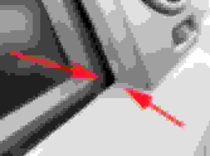
First is the bottom mounting plate fitment. Both displays have a thin plate mounted to the underside for fitting into the dash. Use the D3 plate on the new display for a "proper" fit and toss aside the D4 plate. You will need to drill two holes and remove some metal work. In the image below a red arrow points to the back edge of the plate. In each boxed area is a bit of metal, with a fold, that goes beyond that edge. You need to trim back enough to make that edge one continues line. This will then allow the plate to sit flat on the bottom of the display. The two blue arrows are where you drill mounting holes. Just two screws will be fine for mounting, surprisingly. My holes were off and bit wonky. But the original screws have large pan heads. If needed use a washer. The nice thing about an over-sized hole is being able to perfectly align the plate before locking it down. The trailing edge of the plate should be touching the display (red arrow). Once in hand you will see what I mean. You can also use the D4 plate as a template onto the D3 plate for drilling holes. In the second image, note these small metal tabs that are on the display itself, you need to simply bend these at 90 degrees or more to allow the plate to site flat. You can also trim them off but I a not a fan of cutting metal parts on a box containing electronics.
Next is modifying the bezel around the display. Some have gotten the original D3 bezel to fit. Of course then you end up with two dead buttons in front. Also if doing so keep in mind your screen angle is different and the plate modification above will have to differ. This may also be the case when using a Sport bezel. I am using the original D4 bezel which is black and boring (I do like the fake metal on the Sport though). This is when a Dremel can really come in handy as much trimming is needed. I dont have measurements, so here are some pics to help you trim things up. Really the only critical cut is the lower edge since that needs to fit into the dash surround trim. The first pic shows how I slightly trimmed the surround, to sharpen its corners. But this is really not needed if you round off the corners well on the display bezel, which I also did.
The last bit of plastic that needs to be trimmed is within the dash itself. This is to better allow the display and its connectors to fit. I trimmed the upper part as mentioned in the original UK thread, basically to the first "step" and it was still not easy getting the display into place. When I remove the display again I plan to trim more out. I feel that the connectors are getting smashed. So I recommend trimming as much as you can as far down as you can. Careful, those are duct vents behind here. The fiber and wire harnesses are also very close by! Use extreme caution!
The last bit of display work needed is to simply hit these ears back. Again I could have drilled them out but you are holding a box with electronics inside. Shavings will not do well in there! And use caution when hitting these back as there is a hard drive in this display. Its not powered up, but you dont want or have to hit this ears hard to get them back. They do not have to be flat. This should conclude all the physical modification needed to fit the D4 display into the dash. Update: In later projects I did remove the unit's metal shell and drill out to remove the "ears". Not required but certainly makes for a cleaner install.
Cable routing:
You need the FAKRA and ABS speed signal wires routed from the MMM under the driver seat and up into the dash. This was not difficult. A snake wire helps to get them through the console. You sorta have to poke around to find a path. I ran a 4-wire shielded cable because I am going to see what attaching the mic input will do, if anything, for the display (I suspect nothing, but it has microphone inputs for a reason). For basic install just the FARKA extension and one wire will do. I recommend shielding them in plastic corrugated wire tubing. You will need to remove the upper center console, which I will not go over here since its covered in numerous other places. The FAKRA cable will simple attach to the existing cable from the antenna then plug into the display. For ABS speed signal you need to take apart the connector and locate the proper green wire since there are several. I cut mine and soldered/heat shrunk the connection. My MMM is getting no ABS signal at all and that does not seem to be an issue. The only thing I had to modify was to trim down a quarter inch of plastic material where my cable ran to allow the forward plastic tray to sit flush. If your cables are smaller than my setup this probably won't be needed. If you want to get fancy you could drill a hole and route it that way.
Ignore the fiber loop above, I like to listen to music when I work and with the display gone the MOST network is dead. The look keeps the network intact.
Making the connections:
Now you have to make the final connections by producing your harness for the display. Since your FAKRA and ABS cables are ran and there is no modification to the MOST fiber, all you need is three more wires! Pretty easy. The pins are labeled on the connectors with tiny little numbers. Keep in mind wire colors are not always the same, pinouts take priority over colors. Disconnect the vehicle battery when doing this work.
From the grey original D3 harness connector still in the dash:
Pin ONE is constant battery 12v positive - purple/blue wire
Pins TWO & THREE are both grounds (negative on battery, both wires joint up a few inches down the harness) - black wires
Pin ELEVEN is standby infomat control from the junction box relay. This relay tells things to power up/down - dark green wire
So those above are the only three required from the original D3 harness.
On the new D4 display:
Pin TWO is ABS speed signal
Pine EIGHT is constant 12v positive
Pin ELEVEN is ground
Pine FOURTEEN is standy infomat relay
* Pins are numbered but very hard to see on the display. Pin 1 will be lower right with pin 7 being lower left. Pin 8 will be upper right with pin 14 big upper left.
Connect pin ONE from D3 harness to pin EIGHT on the display. This should be the upper right pin when viewing the back of the display.
Connect pin TWO or THREE from D3 harness to pin ELEVEN on the display.
Connect pin ELEVEN form the D3 harness to pin FOURTEEN on the display.
***Note: I did also wire in my microphone to match the D4 nav unit diagram. I routed it up from the D3 navigation brain unit under the seat. It had no change in getting the voice command system online. I think it requires a different steering wheel gateway module form a D4, but it would be the wrong CAN bus version, so it would not work anyway. Still investigating.
Once your harness is complete its a simple matter of connecting the FAKRA cable, the connector you made and the MOST fiber. The MOST will be a very tight fit so do it last. If you use the 2x7P connector I used, USE EXTREME CARE WHEN CONNECTING. It is possible to push it in an be offset making all the connections wrong which could result in damage to the display! This is also why I prefer an original connector and will continue to source one. Then connect the battery.
Upon startup the display may take some time to boot the first time. The GPS will take time to acquire a new position and you will probably have to select a new region in the navigation menu. Other than that everything should work if its been hooked up correctly! Enjoy your new display!
Last edited by DakotaTravler; Nov 30, 2020 at 11:29 AM.
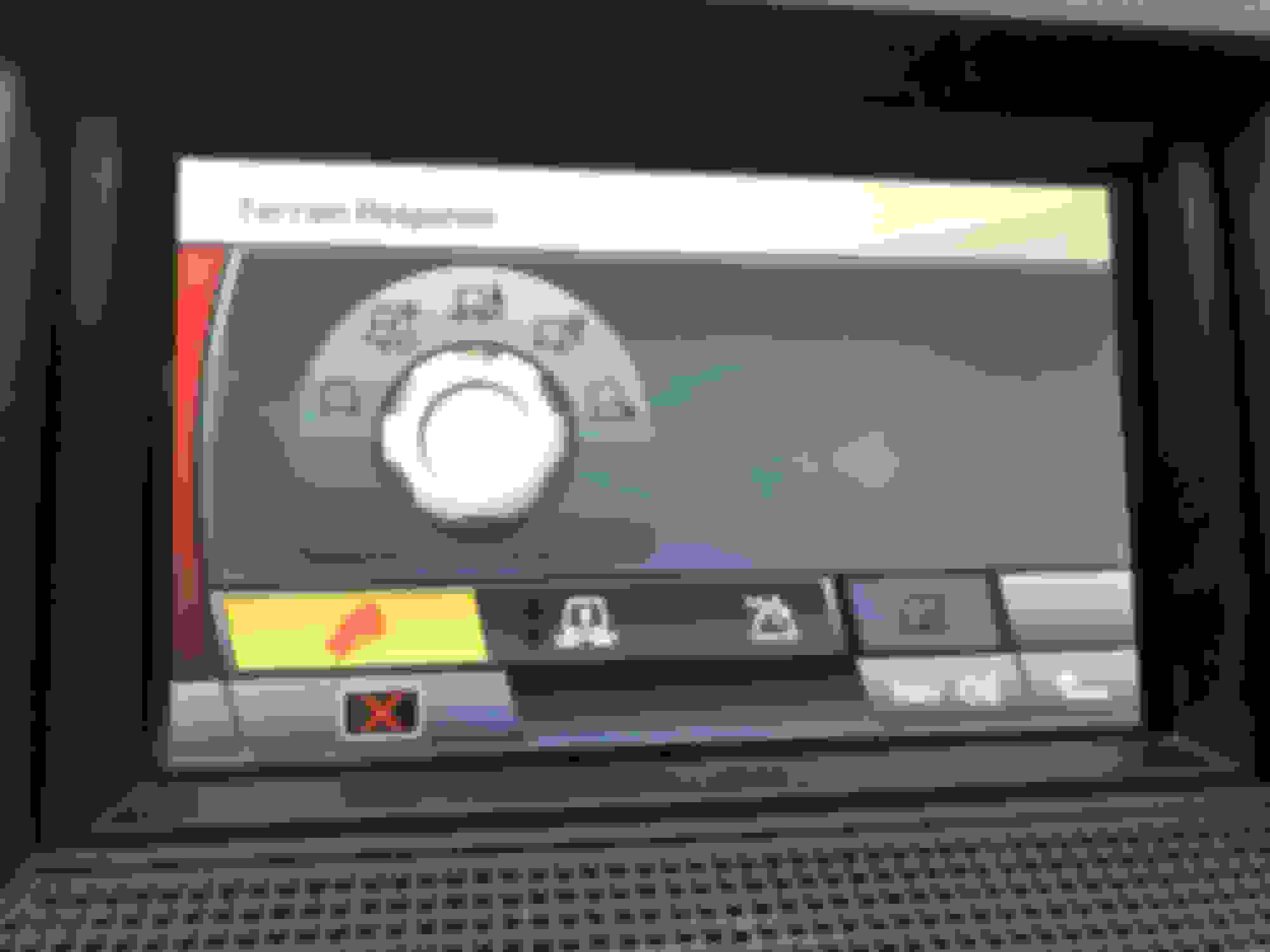
I was playing with the display and never knew you could press the small terrain dial icon on the 4x4 info screen. Can you also do this on a D3 display? Anyway, the small icon does change appearance when I change programs as it did on the D3 display. But if you press the small icon on the 4x4 info screen it brings up a full-sized version of the D4 dial with a few other icons. The other icons, such as hill decent and hi/low gear all work when I make changes. But the dial itself does not show or change in any way when turning the dial. I would expect it to change. Can someone please confirm if the large dial does or does not change? To me this is a total non-issue, but it is something I found.
Tiny update. Today I installed a phone bluetooth module from an LR4 (not music/audio). Not clue how or where the mic gets onto the MOST (I suspect the DVD nav unit under the driver seat?) but no issues and a few nice new features now. First I never have to pair every time I get in. Truck turns off, BT disconnects as it should. Fire it up, phone connects. I not get the carrier name on the radio and nav display. Also signal strength on both. And now the phonebook function of the new D4 nav display works. I can separch, etc. Phone steering button for ending calls works too. Overall just the functionality couple with the D4 nav display makes the whole thing better. I will actually USE my phone with the truck now! Call quality is great but tons of bass, so I may have to set audio setting for each source not one for all (I think that can be done, not sure).
I will have a thread next week on doing the upgrade. Its easy, so it will be a short write-up.
@HILLS - Not sure how I missed your response to my post here, but thanks! I will dig further into finding that connector at a better price. The connector I used I got from amazon (just search 2x7p), its not really a connector since it does not clip in place. For that reason, I dont like it but its stayed connected just fine even though I have had the truck through some pretty rough stuff and corrugated roads.
Small update for everyone. I dont think I mentioned there is so far one annoying drawback, the navigation voice "adjustment" or offset does not stay. Meaning if your music is quiet and you use navigation is comes in full volume. if you adjust while its speaking, it goes down and the radio will show the offset is happening. But the next time it speaks, its back to full volume. I have not dug into seeing if there is a permanent solution and I have also not even checked out the radio head unit settings.
Also now that I have a GAP Tool I have been able to make some CCF adjustments, like activate the Venture Cam and DVD systems. I do NOT have these modules installed but the LR4 Nav unit is clearly reading the CCF just fine and responding to adjustments made.
I have still not found a solution to screen brightness. But I generally just turn the screen off anyway when its annoying me.
I have not been able to active the Portable Audio Player module from the LR4. At this time GAP feels it simply can not be done. I could work if I could somehow install an LR4 radio heat unit, but the CAN buses are different enough that its just not possible. In short my head unit is just not able to see the module on the MOST network so the module powers down and only relays MOST data since it was not given the a-okay by the head unit to be active. I would think GAP could modify my head unit software and make it work but it seems they are not very interested in the LR3 much anymore.
Well it was a pain to locate, lots of spec sheet reading from a few manufactures. But I am 99% sure I sourced the connector. I need to determine the wire pin type and size next so they connector can be made 100% proper to fit. Once I have that all figured out I may make some kits for people to use to convert.