
disco 2 rear ac wring q's


Thread Starter
|
Three Wheeling
Joined: Feb 2014
Posts: 91
Likes: 0
Hey guys, I stripped out a local land rover for rear jump seats and rear ac to retrofit into my 02 disco 2 and need help with the wiring. I have everything else figured out. I am taking before, during and after pics and plan on doing a basic how to walk through which is badly needed on these forums and way past due
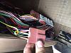
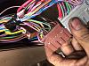
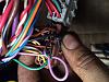
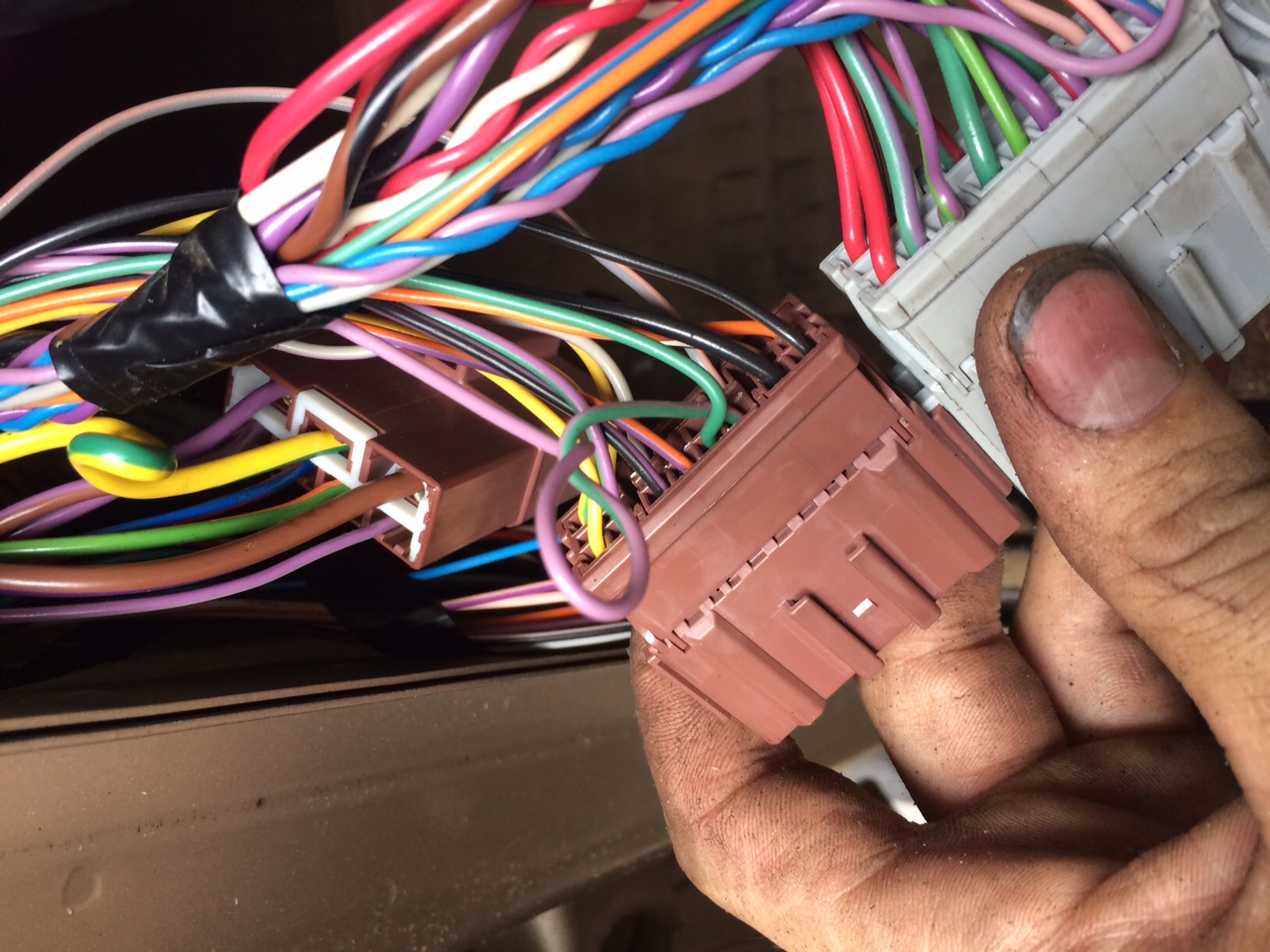
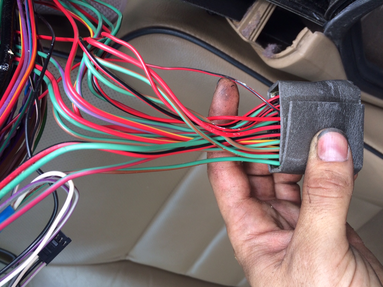
The wires in question go to a plug behind the plastic panel by the hood release handle.
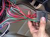
One is a larger yellow wire with a green stripe, another is a medium sized black wire with a green stripe, the 3rd is a small green wire with a pink stripe and last is a light purple or pink with green stripe.
Here are some pics where the go before I cut them off the donor car. The last pic is a small red with black stripe wire that goes to what looks like a terminal power block above the headliner if someone could confirm.
Any help would be greatly apprecaite as I'm excited to get this done and share it with everyone.
The wires in question go to a plug behind the plastic panel by the hood release handle.
One is a larger yellow wire with a green stripe, another is a medium sized black wire with a green stripe, the 3rd is a small green wire with a pink stripe and last is a light purple or pink with green stripe.
Here are some pics where the go before I cut them off the donor car. The last pic is a small red with black stripe wire that goes to what looks like a terminal power block above the headliner if someone could confirm.


Any help would be greatly apprecaite as I'm excited to get this done and share it with everyone.
Recovery Vehicle
Joined: Dec 2012
Posts: 942
Likes: 29
From: St. James, NY
Looking at AC elect diagram (page 38.1) in the RAVE, there is a Yellow/Green wire that goes from Fuse 6 (C0585-1) to the the Relay blower - Rear (R214) via C0485-2 C0480-2
C0691-2 C0857-2
C0480 C0485 Description: Main harness to body harness Location: RH 'A' post
C0691 Description: Rear A/C harness to body harness Location: Luggage compartment - LH side
C0857 Description: Rear A/C harness to body harness Location: Behind LH rear trim panel
C0691-2 C0857-2
C0480 C0485 Description: Main harness to body harness Location: RH 'A' post
C0691 Description: Rear A/C harness to body harness Location: Luggage compartment - LH side
C0857 Description: Rear A/C harness to body harness Location: Behind LH rear trim panel
Recovery Vehicle
Joined: Dec 2012
Posts: 942
Likes: 29
From: St. James, NY
Rear Air Conditioning Operation
Rear Blower relay
A feed from fusible link 4 in the engine compartment fusebox is connected by an NK wire to the passenger compartment fusebox. The feed passes through fuse 6 in the the passenger compartment fusebox and is connected by a YG wire to the contacts of the rear blower relay.
A feed from fuse 31 in the passenger compartment fusebox is connected on a GK wire, via header C0289 (RHD only), to connector interface C0692-4/C0856-4. From the connector interface the feed continues on a WG wire to diode (G126). From the diode the feed is connected on a U wire, through splice joint A48, to the coil of the rear blower relay.
The coil of the rear blower relay is connected on a PG wire to the rear air conditioning switch. The contacts of the rear blower relay are connected on a B wire to earth header C0707, via splice joint A52 when the relay coil is de-energised.
When the rear air conditioning switch is operated, the rear blower relay coil is energised, closing the relay contacts. This allows the feed from fusible link 4 in the engine compartment fusebox to pass through the relay to operate the rear blower motor on an NR wire.
Rear air conditioning switch
When the rear A/C switch is operated, an earth path is completed from the switch on a BR wire to the rear blower switch. The completion of the earth path energises the coil of the rear blower relay and illuminates the switch ON illumination.
The completion of the earth path is also used by the ATC ECU to sense when rear A/C has been selected on. A PG wire is connected from the rear A/C switch, via splice joint A58, to ATC ECU pin C0792-13.
From splice joint A48, the feed from fuse 31 is also connected on a U wire to connector interface C0856-3/C0692-3. From the connector interface the feed is connected to the on/off illumination of the rear air conditioning switch on a WG wire.
Rear blower motor
The rear blower motor is connected on a G wire to splice joint A44. From splice joint A44 the motor is connected on G wires to the rear blower switch and the resistor pack.
Rear blower switch
The rear blower switch is a four position switch which controls the speed of the rear blower motor through a resistor pack.
With the switch in position 1, the earth path for the rear blower motor cannot pass through the rear blower switch. The earth path is through a fusible link and three resistors in the resistor pack to earth header C0707 on a B wire. This causes the rear blower motor to operate at the slowest speed.
With the switch in position 2, the earth path for the rear blower motor is through the fusible link and two resistors in the resistor pack to the switch on an N wire. The switch is connected to earth header C0707 on a TB wire. This causes the rear blower motor to operate at the second slowest speed.
With the switch in position 3, the earth path for the rear blower motor is through the fusible link and one resistor in the resistor pack to the switch on a Y wire. The switch is connected to earth header C0707 on a B wire. This causes the rear blower motor to operate at the second fastest speed.
With the switch in position 4, the earth path for the rear blower motor is direct to the rear blower switch on a G wire, by-passing the resistor pack. This allows full power to flow through the motor which operates at its fastest speed.
Last edited by acamato; Aug 10, 2015 at 09:19 AM.


Rock Crawling
Joined: Jul 2015
Posts: 257
Likes: 15
Rear Air Conditioning Operation
Rear Blower relay
A feed from fusible link 4 in the engine compartment fusebox is connected by an NK wire to the passenger compartment fusebox. The feed passes through fuse 6 in the the passenger compartment fusebox and is connected by a YG wire to the contacts of the rear blower relay.
A feed from fuse 31 in the passenger compartment fusebox is connected on a GK wire, via header C0289 (RHD only), to connector interface C0692-4/C0856-4. From the connector interface the feed continues on a WG wire to diode (G126). From the diode the feed is connected on a U wire, through splice joint A48, to the coil of the rear blower relay.
The coil of the rear blower relay is connected on a PG wire to the rear air conditioning switch. The contacts of the rear blower relay are connected on a B wire to earth header C0707, via splice joint A52 when the relay coil is de-energised.
When the rear air conditioning switch is operated, the rear blower relay coil is energised, closing the relay contacts. This allows the feed from fusible link 4 in the engine compartment fusebox to pass through the relay to operate the rear blower motor on an NR wire.
Rear air conditioning switch
When the rear A/C switch is operated, an earth path is completed from the switch on a BR wire to the rear blower switch. The completion of the earth path energises the coil of the rear blower relay and illuminates the switch ON illumination.
The completion of the earth path is also used by the ATC ECU to sense when rear A/C has been selected on. A PG wire is connected from the rear A/C switch, via splice joint A58, to ATC ECU pin C0792-13.
From splice joint A48, the feed from fuse 31 is also connected on a U wire to connector interface C0856-3/C0692-3. From the connector interface the feed is connected to the on/off illumination of the rear air conditioning switch on a WG wire.
Rear blower motor
The rear blower motor is connected on a G wire to splice joint A44. From splice joint A44 the motor is connected on G wires to the rear blower switch and the resistor pack.
Rear blower switch
The rear blower switch is a four position switch which controls the speed of the rear blower motor through a resistor pack.
With the switch in position 1, the earth path for the rear blower motor cannot pass through the rear blower switch. The earth path is through a fusible link and three resistors in the resistor pack to earth header C0707 on a B wire. This causes the rear blower motor to operate at the slowest speed.
With the switch in position 2, the earth path for the rear blower motor is through the fusible link and two resistors in the resistor pack to the switch on an N wire. The switch is connected to earth header C0707 on a TB wire. This causes the rear blower motor to operate at the second slowest speed.
With the switch in position 3, the earth path for the rear blower motor is through the fusible link and one resistor in the resistor pack to the switch on a Y wire. The switch is connected to earth header C0707 on a B wire. This causes the rear blower motor to operate at the second fastest speed.
With the switch in position 4, the earth path for the rear blower motor is direct to the rear blower switch on a G wire, by-passing the resistor pack. This allows full power to flow through the motor which operates at its fastest speed.
Rear Blower relay
A feed from fusible link 4 in the engine compartment fusebox is connected by an NK wire to the passenger compartment fusebox. The feed passes through fuse 6 in the the passenger compartment fusebox and is connected by a YG wire to the contacts of the rear blower relay.
A feed from fuse 31 in the passenger compartment fusebox is connected on a GK wire, via header C0289 (RHD only), to connector interface C0692-4/C0856-4. From the connector interface the feed continues on a WG wire to diode (G126). From the diode the feed is connected on a U wire, through splice joint A48, to the coil of the rear blower relay.
The coil of the rear blower relay is connected on a PG wire to the rear air conditioning switch. The contacts of the rear blower relay are connected on a B wire to earth header C0707, via splice joint A52 when the relay coil is de-energised.
When the rear air conditioning switch is operated, the rear blower relay coil is energised, closing the relay contacts. This allows the feed from fusible link 4 in the engine compartment fusebox to pass through the relay to operate the rear blower motor on an NR wire.
Rear air conditioning switch
When the rear A/C switch is operated, an earth path is completed from the switch on a BR wire to the rear blower switch. The completion of the earth path energises the coil of the rear blower relay and illuminates the switch ON illumination.
The completion of the earth path is also used by the ATC ECU to sense when rear A/C has been selected on. A PG wire is connected from the rear A/C switch, via splice joint A58, to ATC ECU pin C0792-13.
From splice joint A48, the feed from fuse 31 is also connected on a U wire to connector interface C0856-3/C0692-3. From the connector interface the feed is connected to the on/off illumination of the rear air conditioning switch on a WG wire.
Rear blower motor
The rear blower motor is connected on a G wire to splice joint A44. From splice joint A44 the motor is connected on G wires to the rear blower switch and the resistor pack.
Rear blower switch
The rear blower switch is a four position switch which controls the speed of the rear blower motor through a resistor pack.
With the switch in position 1, the earth path for the rear blower motor cannot pass through the rear blower switch. The earth path is through a fusible link and three resistors in the resistor pack to earth header C0707 on a B wire. This causes the rear blower motor to operate at the slowest speed.
With the switch in position 2, the earth path for the rear blower motor is through the fusible link and two resistors in the resistor pack to the switch on an N wire. The switch is connected to earth header C0707 on a TB wire. This causes the rear blower motor to operate at the second slowest speed.
With the switch in position 3, the earth path for the rear blower motor is through the fusible link and one resistor in the resistor pack to the switch on a Y wire. The switch is connected to earth header C0707 on a B wire. This causes the rear blower motor to operate at the second fastest speed.
With the switch in position 4, the earth path for the rear blower motor is direct to the rear blower switch on a G wire, by-passing the resistor pack. This allows full power to flow through the motor which operates at its fastest speed.

Mudding
Joined: Sep 2016
Posts: 111
Likes: 4
Hey, sorry for reviving this after such a long time but i really need some details about wiring of the rear ac as im in the process of acquiring all the parts needed. Got the blower and ducting, looking for the ac pipes but im not sure what i will need in terms of wiring looms. so from the this question i can deduce that all the wiring for the rear ac is missing? including the wiring to the blower and to the switch panel in the roof? any help/photos would be greatly appreciated.
Thread Starter
|
Three Wheeling
Joined: Feb 2014
Posts: 91
Likes: 0
I actually have all the parts if you are still looking. Lmk
Hey, sorry for reviving this after such a long time but i really need some details about wiring of the rear ac as im in the process of acquiring all the parts needed. Got the blower and ducting, looking for the ac pipes but im not sure what i will need in terms of wiring looms. so from the this question i can deduce that all the wiring for the rear ac is missing? including the wiring to the blower and to the switch panel in the roof? any help/photos would be greatly appreciated.