When you click on links to various merchants on this site and make a purchase, this can result in this site earning a commission. Affiliate programs and affiliations include, but are not limited to, the eBay Partner Network.
Cruise Control: Good pump, good lines, good actuator...
Hi everyone,
Trying to revive the cruise control on my 1999 Discovery 1 SD.
1. I pulled the vacuum pump and made sure it worked by connecting it directly to the battery.
Result: pump was able to create vacuum
2. Connected the vacuum pump to the actuator using new vacuum line and again connected pump to battery.
Result: actuator contracted and suction was maintained until I released my finger from the white valve of the vacuum pump
3. Next, I tested electrical connector to the vacuum pump (Test D1 from electrical manual).
Result: 0V (I should’ve gotten battery voltage)
So I went behind the glove box and started testing the ECU figuring the problem was most likely not the wiring for the vacuum pump electrical connector, but that it might be something wrong with the ECU itself.
4. I performed test B1 and B2
Result: Passed both tests
As a result of passing those two tests it means (per the electrical manual) that the Cruise Control Switch, GLG wire, WY wire, and F18 Fuse are all working (because failure of any of these would’ve meant I wouldn’t have passed the B1 test).
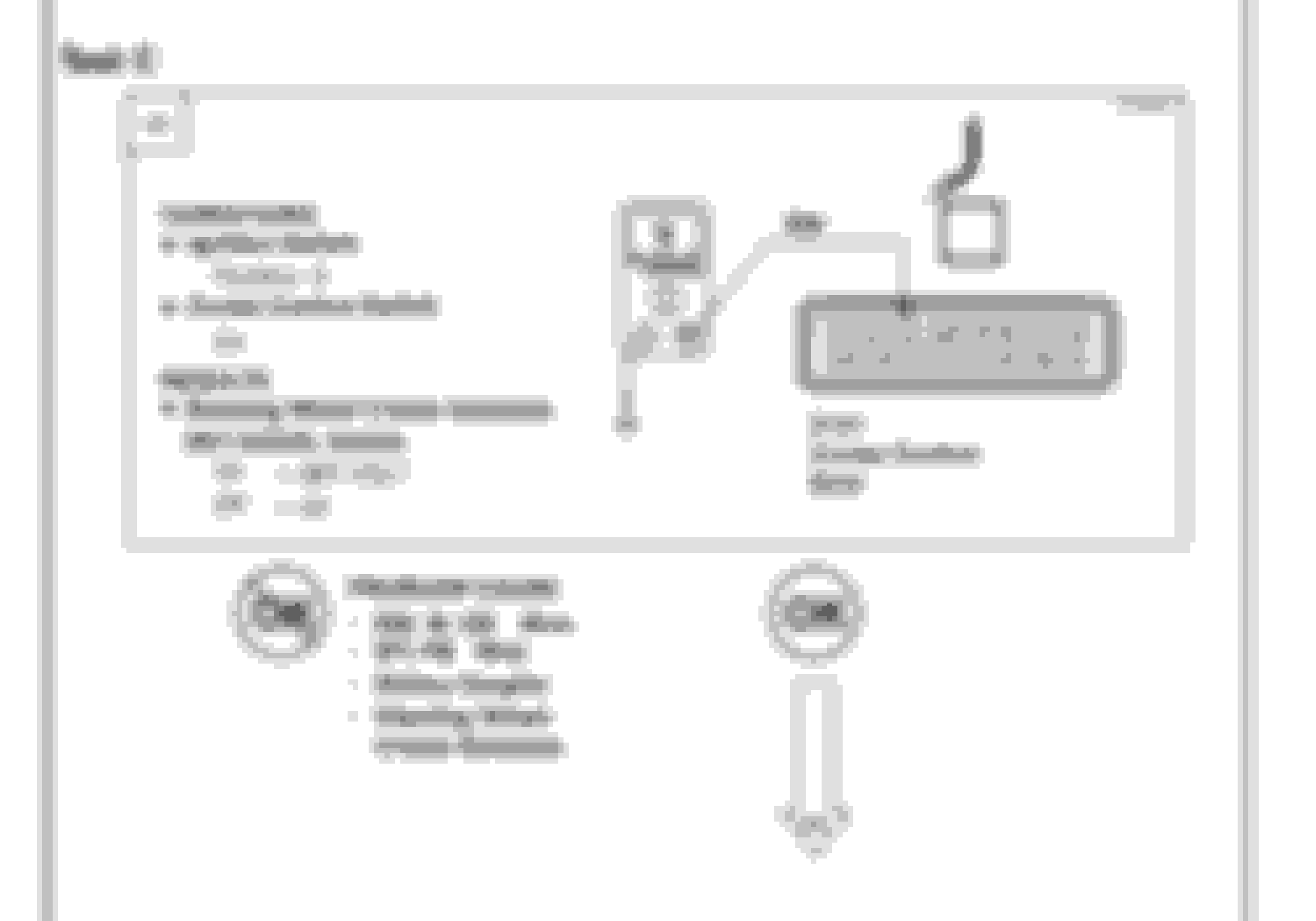
Next, I was directed to test C1 which is where I’m currently stuck. The test instructs you to have the ignition off, cruise control switch on, and then when you push the SET/ACCEL switch on the steering wheel and the multimeter should show battery voltage coming out of port 3 of the ECU module...
Result: I couldn’t produce a positive battery voltage when depressing the SET/ACCEL switch on the steering wheel.
However, with the ignition off (position 0) why would there be a positive 12V for setting the cruise control....?
I know that was a lot, I apppreciate any and all feedback! Thank you!
***UPDATE***
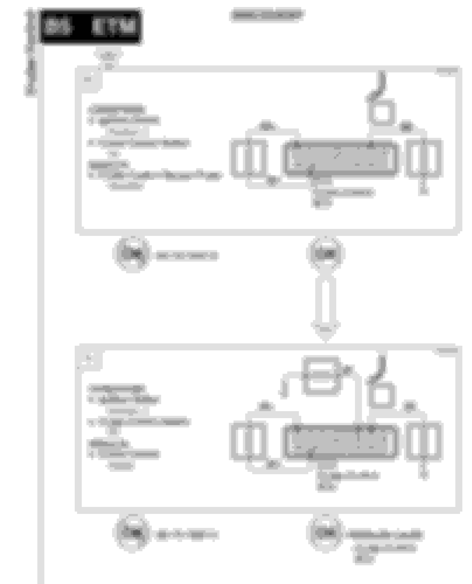
I did Test 6C and 7C(see below). For both tests the result was that my vacuum pump turned on indicating that I passed test 6C, however I’m not really sure what it means for Test 7C as you can see under the result it simply says, “Cruise Control (Right)”. I don’t really know what the “right” means, it was actually pretty frustrating as I sat there and pondered all the things Land Rover was attempting to communicate. So I don’t know whether or not I passed Test 7C, but my current theory is that because nothing changed and the vacuum pump still turned on that most likely this means my cruise control ECU is not working. I ordered a D2 ECU with pigtail.
***UPDATE***
Cruise control is working!
I ended up getting a D2 cruise control unit to replace my AMR 1173 D1 CC ECU. I purchased the D2 ECU with a pig tail and cut out my old D1 connector and connected the wires to the new D2 wire harness.
However, as one person in the thread above mentioned the color code for the D1 breakdown isn’t the same for everyone as some people have different colors. My D1 CC ECU cable colors did not match what EricTyrrell had posted, but the pins were correct aka pin 1-11 performed the function that EricTyrrell states that it does in his post, the color of my cables just didn’t match up. For those of you coming after me here is the color coding for my...
D1 CC ECU (AMR 1173) wiring:
Pin 1: Actuator Pump Power (White/Blue)
Pin 2: Not in use
Pin 3: Set Button (White/Red)
Pin 4: Resume Button (Purple/White)
Pin 5: Brake Light Switch (Green/Purple)
Pin 6: Actuator Valve Control (Black/Yellow)
Pin 7: Actuator Pump Control (Black/Red)
Pin 8: Ground (Black)
Pin 9: Brake Pedal Vent Switch (Purple/Green)
Pin 10: ECU Power (White/Yellow)
Pin 11: Speed Signal (Yellow/White)
For those of you new to electronics, the first color listed is the predominant color while the second color listed will be a thin strip as compared to the predominant color.
Last edited by DiscoNewbe; Jun 30, 2020 at 05:11 PM.
Reason: Update
You would probably be the only D1 owner here with working cruise control.
Anyone here with a D1 have working cruise?
lol that might be right. I was pretty happy to see the vacuum pump and actuator working, but I�m not sure why when I engage the cruise control switch I�m not getting power to the vacuum pump.
Seeing as the CC ECU is in charge of energizing the vacuum pump (I think) I was banking on the ECU most likely being the culprit. I ordered a D2 ECU today and will do the wiring conversion, but if anyone has any insight I�d appreciate it! Thanks.
Last edited by DiscoNewbe; Jun 23, 2020 at 09:49 PM.
i'm going thru same issues and was playing with it today,97 d1 112k,have two vacuum pumps tried both,really good vacuum lines [no cracks] 2 ecu units,two brake pedal units and 2 engage switches! did you check continuity on the brake pedal switch? you know much more than me about electronics! i left everything open behind glovebox so i guess i'll try testing the wheel switch next,let us know if you figure it out oh and yeah about how many have working cc!! i'm going to use your diagram so just by putting pos pin from multimeter in #3 of connector and with ignition off and pushing set switch i should see 12v on multi-meter?that does sound weird with ignition off but i'll try!
Last edited by rjlsierra; Jun 25, 2020 at 02:51 PM.
i'm going thru same issues and was playing with it today,97 d1 112k,have two vacuum pumps tried both,really good vacuum lines [no cracks] 2 ecu units,two brake pedal units and 2 engage switches! did you check continuity on the brake pedal switch? you know much more than me about electronics! i left everything open behind glovebox so i guess i'll try testing the wheel switch next,let us know if you figure it out oh and yeah about how many have working cc!!
I’m at a standstill until my new ECU arrives, but hopefully it works! I just updated my progress above.
In regards to Test 1C, I haven’t figured out if I was doing something wrong or if the component simply isn’t working. I haven’t checked my brake pedal switches, but while doing one of the tests in the manual that the truck successfully passed it indicated that my brake valve was working properly (not 100% sure what that is)
I’m using the electrical manual that you can get from some of the people posting Rave manual PDF links. If you have an automatic you should be starting with Test B and then it directs which tests to do as you progress through the results.
Last edited by DiscoNewbe; Jun 25, 2020 at 03:05 PM.
D2 cruise control ecu from a gems truck is an easy swap. I spliced on a matching pigtail in case the D2 fails.
It does look like it�s pretty straight forward, just waiting for mine to arrive. What was your reference for making sure you wiring from your D1 corresponded correctly with the new D2 CC ECU? Thanks.
just tried that test ignition off,cc on,pos touching #3 grounded and depressed set switch,got nothing from multimeter,so does that mean my switch at the wheel is bad? did you get 12v when you did your test?sorry went back and re-read and see that you didn't get any reading either,most of the time for me it was always the break pedal switch that's why i said to check continuity,put get in there pull the connector put your multimeter on prongs than push the pin in [mm set to continuity] not easy but it'll tell you if switch is good or just pull the switch out,i'm stuck don't know where to try next [didn't mention but actuator good and holds vacuum.
Last edited by rjlsierra; Jun 25, 2020 at 04:04 PM.
just tried that test ignition off,cc on,pos touching #3 grounded and depressed set switch,got nothing from multimeter,so does that mean my switch at the wheel is bad? did you get 12v when you did your test?sorry went back and re-read and see that you didn't get any reading either,most of the time for me it was always the break pedal switch that's why i said to check continuity,put get in there pull the connector put your multimeter on prongs than push the pin in [mm set to continuity] not easy but it'll tell you if switch is good or just pull the switch out,i'm stuck don't know where to try next [didn't mention but actuator good and holds vacuum.
Yeah, I got no response (0 volts) when I performed that test (Test C1). If you go look at the image above for Test C1 under result for a failed test it lists 4 different things that could be wrong, but as I said before I�m hesitant to believe that I performed the test correctly because it doesn�t seem logical that the test should work with the ignition completely off.
For testing the brake switch you go to the brake pedal, place the your multimeter probes into the back of the connect while it�s still plugged in, and then check for continuity? Do I have that right?
you can do it that way but it's much easier to take out the switch and hold mm on both tabs and push the rod in if you hear the mm make noise the switch should be good [set of course to continuity]