When you click on links to various merchants on this site and make a purchase, this can result in this site earning a commission. Affiliate programs and affiliations include, but are not limited to, the eBay Partner Network.
Basically, that bottom Wye remains where it is with the heater hose & overflow tank return. You remove the LR thermostat and plug you radiator outlet into that spot. So now you have 1 big loop, traditional. Engine outlet/thermostat to radiator inlet, radiator outlet to water pump/engine inlet. The bypass & outboard thermostat housing has been deleted.
It works: my operating temp is a SOLID 183-185 with ambient temps up in the high 80s, low 90s. It will get a little higher when temps hit 100+
So, best way I know how to explain what I missing without going back-and-forth with 100 posts. This is what the current set up looks like. What's the new set up supposed to look like? I have all the parts that were recommended in the post above, just not sure how to put it all together because the pictures didn't cover everything.
you've seen some pics on another thread, haven't you? I just have a few old shots as I no longer have 1 of those fancy, portable phones anymore. Now I have the temp sender adapter before the thermostat, but I still have the exact same parts.
So, best way I know how to explain what I missing without going back-and-forth with 100 posts. This is what the current set up looks like. What's the new set up supposed to look like? I have all the parts that were recommended in the post above, just not sure how to put it all together because the pictures didn't cover everything.
forget about "the 7 hoses," that's why you are confused. Look at it this way:
the very top, front of the engine where your main coolant hose comes out of the manifold to the Tee w/ bleeder screw...instead of having that Tee there, you want 1-hose with a thermostat and modified housing running directly to the top radiator inlet. That's "that."
On the bottom of the radiator outlet, you want 1 updated hose running from there directly to the plastic Wye fitting at the large point of entry. Assuming you leave the Wye fitting as is with the 2 smaller hoses undisturbed to their factory locations, you remove the largest, OEM hose, fit your new modified hose that comes directly from the lower radiator. Everything else gets tossed.
If you read this while you are looking at your engine you should be able to figure it out.
If I put the two hoses from the y-pipe to their factory locations, one goes to the reservoir which is fine but the other goes to the old thermostat which obviously won't work. If I'm understanding correctly, this is what the new set up should look like.
I apologize for not checking back sooner. Got real busy in April. Just started getting some free time back.
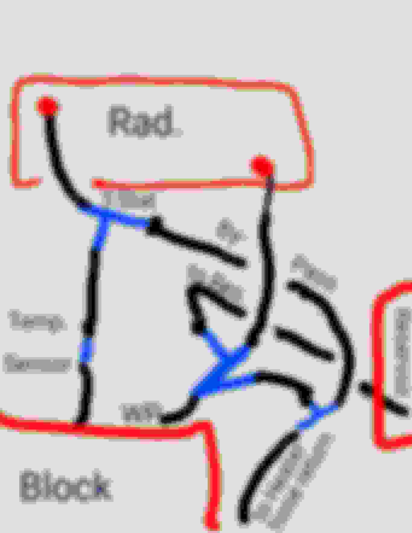
I'm attaching a sketch of the routing. The missing hose above is the heater hose return. The factory hose (molded) has two smaller hoses integrated. One to reservoir and the other to the heater hose return.
My routing tees the bypass with the heater hose and connects to the glass reinforced nylon connector that my replacement lower hose came with (in place of oem molded). The other connection goes to the reservoir, of course.
Btw, I forgot to draw in the aluminum tee between the nylon connector and the radiator. It is for a BMW style dual temp fan sensor for the Taurus electric fan. The routing lengths for all hoses are exaggerated .
The setup is an inline thermostat, but with the Ford style bypas thermostat. The purpose of the bypass is to divert engine return coolant directly back to the water pump to heat the engine quicker when cold. It reduces engine wear and gets the emissions leveled off quicker. Once engine hits thermostat limit, all coolant is shunted to the radiator. The bypass doesn't lower high temps, it simply aids with emissions and engine longevity (and heater gets warm quick in winter).
Inline thermostat with warm up bypass added.
If I put the two hoses from the y-pipe to their factory locations, one goes to the reservoir which is fine but the other goes to the old thermostat which obviously won't work. If I'm understanding correctly, this is what the new set up should look like.
Like I said, if you leave the lower 3-way fitting in place, the 2 smaller hoses that go to reservoir & heater matrix/block remain unchanged. If you remove the larger inlet hose from the factory thermostat to the Wye fitting & plug in a new, updated hose connected directly to the lower radiator outlet you would then have a traditional routing: radiator outlet to water pump & engine block. A deleted bypass. Your interpretation of the upper hose modification is correct.
Which hoses you use & how you get there is mostly your own preference but the whole concept is to make 1 big traditional loop. The engine manifold outlet (aka coolant outlet elbow for D2) directly to upper radiator inlet. The lower radiator outlet directly to the water pump. The lower Wye fitting is just easier to leave in place so that the coolant header tank and heater return (smaller 2 hoses @ Wye fitting) remain connected to the system without further modification.
I apologize for not checking back sooner. Got real busy in April. Just started getting some free time back.
I'm attaching a sketch of the routing. The missing hose above is the heater hose return. The factory hose (molded) has two smaller hoses integrated. One to reservoir and the other to the heater hose return.
My routing tees the bypass with the heater hose and connects to the glass reinforced nylon connector that my replacement lower hose came with (in place of oem molded). The other connection goes to the reservoir, of course.
Btw, I forgot to draw in the aluminum tee between the nylon connector and the radiator. It is for a BMW style dual temp fan sensor for the Taurus electric fan. The routing lengths for all hoses are exaggerated .
The setup is an inline thermostat, but with the Ford style bypas thermostat. The purpose of the bypass is to divert engine return coolant directly back to the water pump to heat the engine quicker when cold. It reduces engine wear and gets the emissions leveled off quicker. Once engine hits thermostat limit, all coolant is shunted to the radiator. The bypass doesn't lower high temps, it simply aids with emissions and engine longevity (and heater gets warm quick in winter).
Inline thermostat with warm up bypass added.
---------
If you have tried inline T-stat to a Rover before then you will know that engine warm up not only doesn't take longer with this mod but it's even faster than before, from stone cold it takes 2 min to get to 140*f and you have good heat in engine, so if someone told you otherwise they have not experiment with it yet. (Both my disco's react almost identical with inline mod).
So the extra by-pass you are doing will not help it get warmer sooner, & if by-pass doesn't close completely when T-stat opens then the Beautiful radiator that you have bought (& honestly I love the look of it & I know it will perform even better than it looks) will not be able to do its job,,
If I didn't have new radiator's on both disco's, & I needed to get a new one, I would definitely buy one like yours, but for now I have added a small radiator in front of original one & it works in-line with main radiator, it doesn't do anything in traffic or city driving cause truck runs cool at those speeds even in hot weather with AC on anyway,, But It show's its benefit at high speeds 80 and up when going long incline's in Hwy,,,
Okay some pictures of my change to a different thermostat and radiator. I am currently mounting the radiator and electric fan, so hoses are temporarily out waiting for radiator to get final location for fitment of hoses
Transition bypass hose 1 1/2" tee with dual temp sender
.
Radiator is a Griffin 45241, made in USA, all aluminum. Griffin is top notch, used by racers. It has three inches to spare both sides, so a slightly bigger radiator will fit. Thermostat will be attached to back of electric fan for support (has some heft to it, needs securing) about same location as factory thermostat. Bypass outlet (1 1/4") is attached to the transition hose, which is attached to the 3/4" brass tee. Other side of tee is about 8-9" of hose to metal heater return pipe. Tee connects to the nylon connector closest to water pump (active coolant running through engine, heater and bypass) and hotter than the coolant in expansion tank. Trying to keep temperature separation from fan temp sender (bypass coolant hotter than radiator outlet coolant). Dual temp sender is between nylon connector and radiator outlet.
The factory tee with bleeder is currently retained with a cap on the tee. May upgrade to metal tee and metal bleeder, later. A temp sensor added before thermostat to read temps from engine.
The upper coolant hose is retained, however, I am cutting it between the clips on the molded radiator cover. I am rotating (with union) the part that goes to the tee and pointing it downward through the factory hole in the factory cover (normally covered by hose and not seen) to connect to the thermostat housing outlet to radiator. There is some interference with factory routing near radiator inlet with the electric fan, but doable.
Radiator outlet Inlet Griffin radiator 45241 Ford thermostat bypass housing, temp sensor, replacement factory tee with bleeader with tee to be capped. Stat housing over Nylon connector from replacement hose, 3/4" tee added for heater return and bypass return, other connection for expansion tank hose. Nylon connector, other side.
Did you get the 180* thermostat for the Ford housing and have you completed the installation yet??

 05-02-2017, 12:28 AM