Lucky 8’s Project P38

#54
 01-19-2013, 09:39 PM

project update
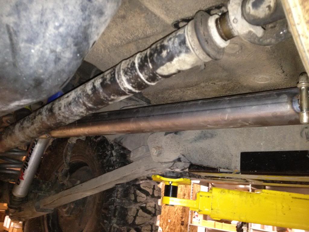
The exhaust was the next thing we had to address. Everything from the cats back was removed by rocks at our last event.
For some reason this part of the Y pipe drops lower than anything else on the truck. It had been crushed and bent from an obstacle we went over. I really think we are going to have to make some sort of skid plate to protected in the future.
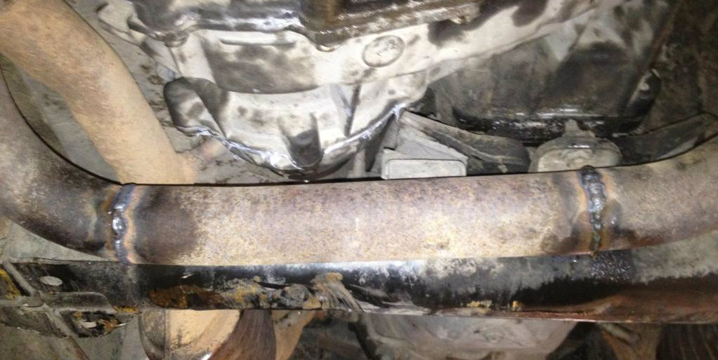
And the last thing to repair was this mid muffler section. You can see another off-road faux pas with Land Rovers design right here. This muffler use to hang lower than the frame.
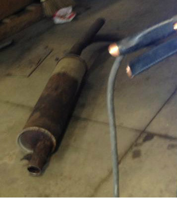
With it out of the way we put in a straight pipe that sits much higher than the frame. This should help us avoid any future damage
The exhaust was the next thing we had to address. Everything from the cats back was removed by rocks at our last event.
For some reason this part of the Y pipe drops lower than anything else on the truck. It had been crushed and bent from an obstacle we went over. I really think we are going to have to make some sort of skid plate to protected in the future.
And the last thing to repair was this mid muffler section. You can see another off-road faux pas with Land Rovers design right here. This muffler use to hang lower than the frame.
With it out of the way we put in a straight pipe that sits much higher than the frame. This should help us avoid any future damage
#58
01-22-2013, 10:19 PM
project update
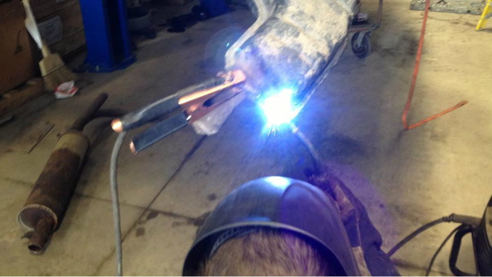
We have been racking our brains on how to lock the viscous coupling. There are a few ideas out there on how to make this possible but the expense is making it cost prohibitive. To make matters worse I don't know if the front output shaft is strong enough to handle being fully locked. But as the old saying goes when the going gets tough the tough get going. So we built a jig, welded the viscous coupling in the correct locked position and installed it in the transfer case.
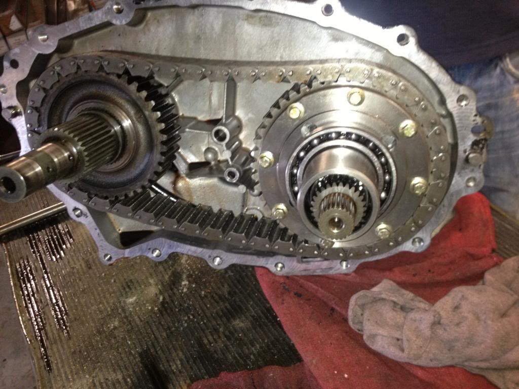
By doing this we will be able to find out if the front output shaft is strong enough to handle the load put on it when the transfercase is locked. If it doesn't explode we will continue to look for viable options to lock the T case. The best way to show that the transfer case is locked on a Borg-Warner box is to pull the front driveshaft and see if the truck will still move, and thats exactly what we did in this video.
Your first take on the video maybe just a yahoo having fun in the snow, but when you really look at it our P38 is spinning the rear tires while the front tires remain stationary. This means the transfercase is locked and all the power is going to the rear output shaft without causing an explosion. I'm pretty confident that the rear will hold up okay. We have been driving the truck around as a rearwheel drive unit for about a week without any side effects.
We have been racking our brains on how to lock the viscous coupling. There are a few ideas out there on how to make this possible but the expense is making it cost prohibitive. To make matters worse I don't know if the front output shaft is strong enough to handle being fully locked. But as the old saying goes when the going gets tough the tough get going. So we built a jig, welded the viscous coupling in the correct locked position and installed it in the transfer case.
By doing this we will be able to find out if the front output shaft is strong enough to handle the load put on it when the transfercase is locked. If it doesn't explode we will continue to look for viable options to lock the T case. The best way to show that the transfer case is locked on a Borg-Warner box is to pull the front driveshaft and see if the truck will still move, and thats exactly what we did in this video.
Your first take on the video maybe just a yahoo having fun in the snow, but when you really look at it our P38 is spinning the rear tires while the front tires remain stationary. This means the transfercase is locked and all the power is going to the rear output shaft without causing an explosion. I'm pretty confident that the rear will hold up okay. We have been driving the truck around as a rearwheel drive unit for about a week without any side effects.
#59
01-22-2013, 10:36 PM

The old Lincoln Locker. Hope the welds don't break on the coupling like they sometimes do on welded differential carriers. Of course, I imagine you put a little thought into how you prepped the piece for welding.
How does your traction control like that setup? Doesn't the computer get pissed off with such disparity between reading in the front and rear and start trying to lock the brakes? I used to do donuts in the snow in my P38 with the full driveline in and it worked pretty well but it seemed that all the wheels got in on the act.
How does your traction control like that setup? Doesn't the computer get pissed off with such disparity between reading in the front and rear and start trying to lock the brakes? I used to do donuts in the snow in my P38 with the full driveline in and it worked pretty well but it seemed that all the wheels got in on the act.
#60
02-08-2013, 08:14 PM