When you click on links to various merchants on this site and make a purchase, this can result in this site earning a commission. Affiliate programs and affiliations include, but are not limited to, the eBay Partner Network.
My 05 LR3 has been lit up like a Christmas tree for over a year, and I'm finally taking the time to work on the issue. Hopefully some of y'all can help me out.
Background:
I purchased this Rover over two years ago for a song because the PO started having overheating issues, and he was tired of sinking money into it. Why buy a troubled Rover? He had the transmission rebuilt about 3,000 miles before the overheating issues started. Long story short - I fixed the missing cooling T, rebuilt the top end, and did a full tuneup. Yay, a working Rover!!
All was good for several months, besides the occasional bad coil and no signal from both post cat o2 sensors, until that fateful morning. It was time for an oil change, so I raised her to off road height, changed the oil, and went to bed. When I walked out in the morning, she had lowered to access height, and the dash said Christmas was early. Ugh! The problem was more an issue than not, but occasionally, I'd start her up, and she'd be normal without any faults. That lasted a couple of months, and now there are no good days or trips.
Process so far:
New Interstate battery
New LED stop lamps
New brake switch
Fixed splices in the door sills
etc - you name it, I've probably done it
Current Issues:
I'm driving a manual automatic. I could use "drive," but the shift points are too high for my liking. And forget about auto when she's loading! I also have to trick the EAS to have any sort of comfortable ride. She has what I would call normal air bleeding in the suspension, so every once in a while, I have to put the EAS fuse in, drive until the doors autolock, clear the codes, let her return to normal height, and pull the fuse back out. This gets annoying when I have to pull a trailer. So what does my IID say?
P186D - Clutch Actuator Stuck
P0915 - Gear shift position Range
The P0915 is new - it started showing up since I started trying to calibrate the position and clutch.
Recent Work:
I took the TB motor off, cleaned it out including the brushes, and reinstalled it. I'm able to see motor RPMs, and the HALL sensors seem to show movement. I don't think it's the motor. I can get one shot after startup to try to change the range before I get the "Transmission Fault, Traction Reduced" message. After the first change attempt, the computer doesn't allow any more change attempts unless I turn off the engine and wait 30 seconds.
I've also done extensive logging with my IID. It's not the range switch - there are no issues when I view those values. It shouldn't be too hard to figure out which of the three components (Position Sensor, Solenoid, Motor) has failed.
What I need help with:
What Live Values should I be looking for?
I have the wiring diagram, but what it doesn't say is what path the wires take through the Rover. My concern is the transmission was rebuilt, and it looks like the sensor wires run on top of the transmission. It also appears that the O2 sensor wires run that way (which never show voltage). I haven't found the solenoid Green & Silver wires in the door sills, so I assume they take a different path. How do the three components' wires run to the TCM?
How can I test the solenoid? When I test the resistance on pins 1 & 2, I get 0.8 Ohms... that seems really low to me. I would expect at least 8+. Can I test it that way, and what should a good value be? Can I try to energize it (a feature the IID tool apparently lacks) by hooking it to the battery to see if it actuates? Is it a 12V component?
How can I test the position sensor? Do I just hook my oscilloscope to the position signal pin and graph the output? What would a good trace look like? Can I check it for resistance?
I was busy yesterday, but I took some time this morning to look into #3. I was able to confirm it's 12V by checking the voltage with the ignition on. I was also able to determine that the solenoid is normally energized since it gets power as soon as the ignition is turned on. A quick check of section 308-07A in the manual confirmed this.
Armed with this new information, I set out to see if I could verify the solenoid would actuate. I didn't have high hopes because there is a near short in the solenoid. I took the three bolts off that hold the solenoid using a 5mm socket. I was able to pull back on the solenoid (which makes sense because it's not energized), so I knew it wasn't stuck. I turned the ignition on, and didn't see a change in the solenoid. I confirmed it was getting about 12V at the connector.
Well, there's my problem. I'm going to call the local dealers in the morning to see if they have it in stock, otherwise, I'll have to order it online and wait for it to be shipped from the UK, ugh!
Now I have a new problem... The manual states the solenoid needs to be energized before it can be removed, but mine doesn't actuate. Looks like I'll be having fun trying to get the solenoid out.
I called the local dealers today, but they wanted about $250 for the solenoid... umm, no thank you! I could get it from them in a day or two, but I'm not going to spend an extra $100 for that convenience. I ordered the solenoid from an online USA warehouse that I've never used before for $150 tax, title, and 2 day shipping. Hopefully everything goes good with that - I'll update later if there is an issue.
Originally Posted by abran
Interesting.
i recently rebuilt a t case and left the solenoid in due to the need to energize it to remove.
Please follow up with your solution.
I was able to get the solenoid out even though I couldn't energize it. The trick is to pull it back towards you while pushing the top of it towards the front of the Rover. I basically tilted the base that connects to the TB to the bottom left, and the top end of the solenoid to the top right. The solenoid has a T at the end of the shaft that sits in-between two horseshoe shaped forks is the best way I can describe it. Imagine one horseshoe sits deeper inside the solenoid hole, there's a space where the T sits, and then another horseshoe shaped fork closer to the opening. [T]. When the solenoid is energized, the T will push on the deep fork to activate the multi-clutch mechanism. When the solenoid is not energized, the T is pulled back closed via a spring, and that pulls the other horseshoe towards the solenoid to facilitate the range change.
I'm not one to leave one well enough alone, so with the solenoid in hand, I set out to do some more testing. I had already confirmed that I had about 12 volts at the solenoid connector, but I also knew that the solenoid would not energize. I was wondering what would happen if I hooked the solenoid up directly to the battery. So, I did just that, and guess what... the solenoid energized. Crap, I ordered a part I didn't need, right? No, and let me explain why. While the solenoid did energize when it was hooked directly to the battery, it also got really hot very quickly. Hmmm... Let's take a look at why that is.
If I'm looking for the Indian, I need to look at what the value of the Eagle over the Rabbit is (I=E/R). So, I have 12 Volts, divided by 0.8 Ohms = 15 Amps... Wow!! No wonder the thing was getting hot! There's no way that the Rover would keep that solenoid energized all of the time if it was drawing 15 Amps! But why did the solenoid energize if it's not working? The reason I was able to energize the solenoid when I hooked it directly to the battery is because the solenoid was able to draw from the over 650 amps available in the battery without having to deal with the maximum sink values of the components in the TCM. Having opened the TCM, I know for sure that the components there cannot power much more than about 1/2 an amp.
With all of that new knowledge, lets guess what the coil resistance will be of the new solenoid. Knowing the TCM can only supply a maximum of 0.5 amps, lets see what we get for the Rabbit (R = E / I).12 volts / 0.5 = 24 Ohms. This is what I would consider the absolute minimum resistance of the new solenoid. I doubt a new solenoid would require 0.5 Amps because that would put a huge stress on the TCM components... lets see if we can find something that wouldn't cause too much stress. A more likely value would be to have about a quarter of an amp draw or less, so if we look at those values, we'll see 12 volts / 0.25 amps = 48 ohms. My prediction of viable resistance values of a good, working solenoid would be between 25 and 75 ohms with a higher resistance value being preferred.
Last edited by pos_lr3; Nov 9, 2017 at 08:21 AM.
Reason: formatting
Yeah, yeah... I get it... no pics, it didn't happen...
Here's the diagnosis of the solenoid's resistance...
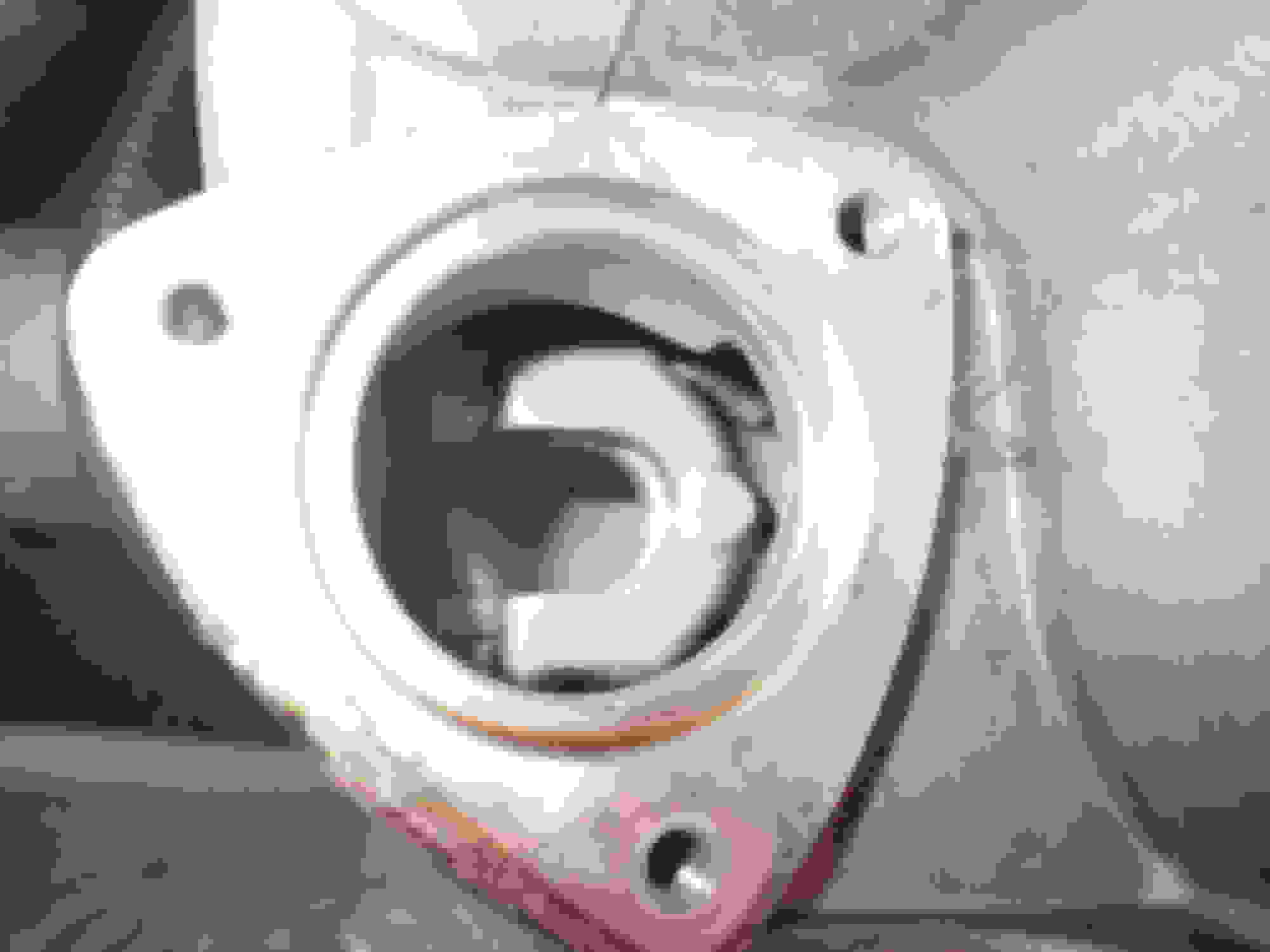
So, it was difficult to describe how the solenoid works with just words... I said... basically, it would be two horseshoes with a groove in the middle... How about a few pictures to help?
As you can see, there is a notch in between the two forks of that clutch arm. How much force does it take to actuate the arm? Very little... the spring inside the solenoid is more than enough to counteract the default position of the forks (extended).
Here's a closer view of the T inside the forks...
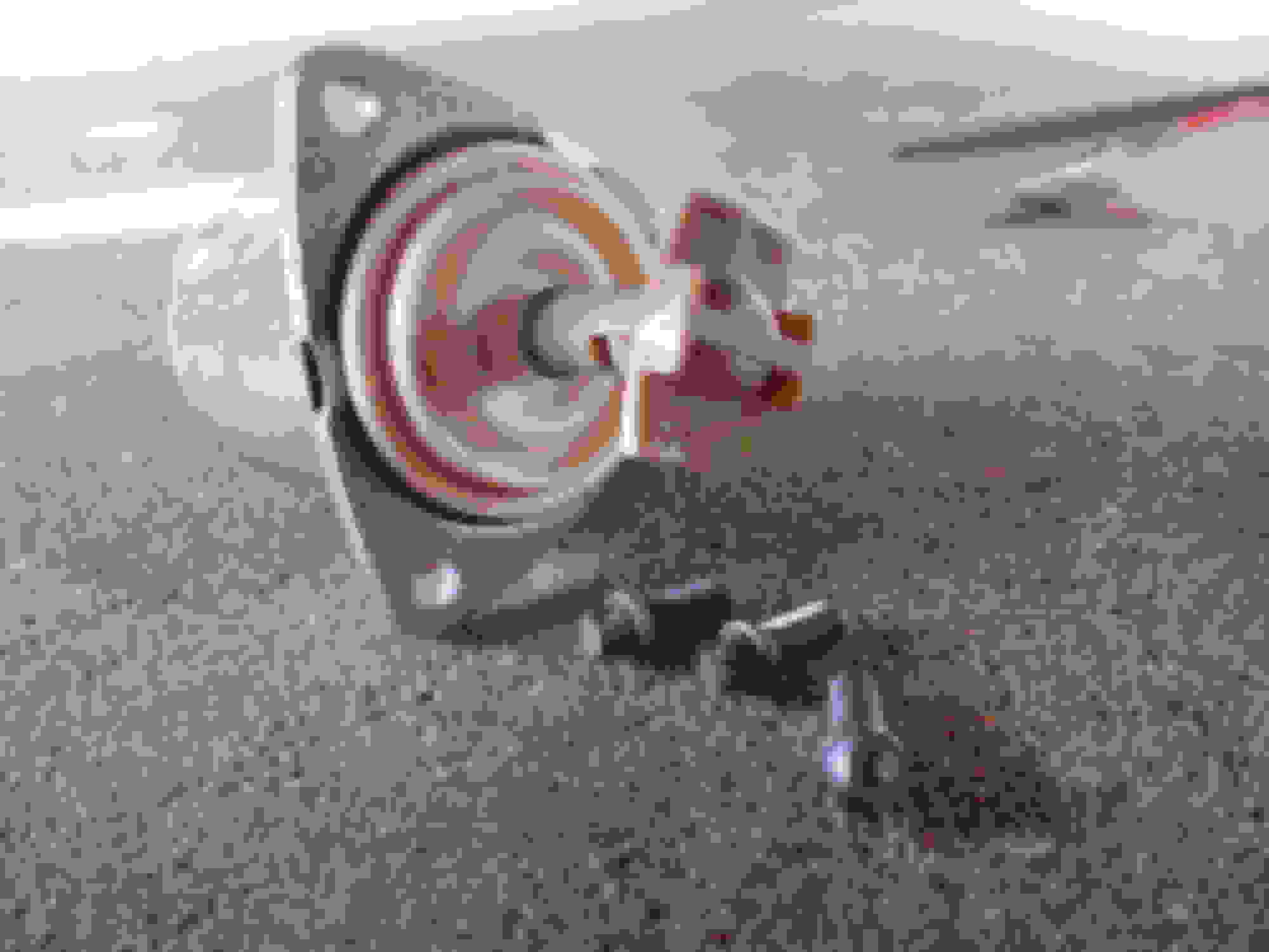
So, what does the solenoid look like when it's removed?
Make note of the flexible gasket I'm holding... This part was stuck to the TB housing. While it was attached, it prevented any fluid from leaking out of the TB. Once I removed the solenoid, I lost about 3-4 oz of fluid... Here's a shot of liquid gold...
For those following along at home, TB = TC = Transfer Box = Transfer Case... Sorry, that's the UK way of looking at things.
Now, on to the update:
So, I felt I was in the best position to figure out what was going on with this solenoid... Let's see what we can sink out of the TCM...
10ma... that's all. Granted, when I hooked everything up, and tried to figure out the amp draw, I saw 1 ma when I turned the key on. Granted, this took me by surprise, until I thought about what was happening... So, basically I have a big coil (an inductor), and I have a bit of parasitic resistance from that coil (about 0.8 ohms)... So what happened? I have a series Resistor-Inductor circuit...
I recognized the exponential charge immediately, and I then waited for the final draw (source of the TCM)... 10 ma. Well, it looks like I need to update my coil prediction. I was hoping for a 1/4 - 1/8 amp draw, but it's looking like the TCM can only source 10 ma... 1200 Ohms. That's my new prediction.
We'll see what happens. I should get my new coil tomorrow. If there's something I didn't get a picture of that you'd like to see, let me know, and I'll make a picture.