
300D Turbo Disco I Complete Build (Adapter Prep)


Adapter plate:
The native Benz adapter plate is smaller than the R380/LT77 bell housing and obviously mounting holes are not going to align. So we need an adapter plate. The thickness of suck a plate dictates the r380 input shaft position / insertion into the crank bore as well as mesh coverage of the splines of the input shaft into the splines of the clutch disk.
The main consideration I had was having enough coverage on my pilot bearing or bushing. Using the outside diameter of the input shaft and the inside bore diameter of the crank, we come up with our new bushing. Rather than messing with milled adapter material to space the flywheel off the crank flange, we need to close the distance between the trans and the motor.
With the invaluable help of Koldstart and his ability to make quick work of a proper mock up in Sketchup, we came to realize that the adapter plate thickness needed to be 3/8 in unlike my original idea of �. Which would open the distance between motor and trans resulting in unsatisfactory contact of all integral drive components inside the bell housing.
Although 1/2inch would work well, the need to extend the pilot means that much further and coverage of clutch splines by input shaft may be effected as well.
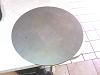
So Here is the Adapter plate material
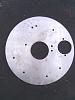
Using the native Benz adapter, I circled and centered crank and starter bores and block mounting holes. Note the original material is the HDPE and NOT the actual plate used in my application. This demonstrates the Benz adapter of which I scrapped and how I transferred the hole references. I forgot to take photos of referencing the holes as it was hella hot in my driveway when i was drilling this thing out.
The crank flange bore is excentric to plate center. When referencing my holes, I tool special notice of the dowel pin location on the block and driled those just after the crank bore. I drilled al other holes reference to those to ensure a good fit when i bolt it on to the motor.
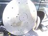
And here I have the complete motor portion of drilling complete.
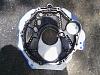
Here I have mounted plate and flywheel.

Actually looks like something now.
Here is my Photobucket album for adapter prep. There tells a story of all materials and ideas i went through and things I had to look at to make this part work.
I am in the process of organizing the photos in there as you read this so if there is something in there that is out of order just disregard.
The native Benz adapter plate is smaller than the R380/LT77 bell housing and obviously mounting holes are not going to align. So we need an adapter plate. The thickness of suck a plate dictates the r380 input shaft position / insertion into the crank bore as well as mesh coverage of the splines of the input shaft into the splines of the clutch disk.
The main consideration I had was having enough coverage on my pilot bearing or bushing. Using the outside diameter of the input shaft and the inside bore diameter of the crank, we come up with our new bushing. Rather than messing with milled adapter material to space the flywheel off the crank flange, we need to close the distance between the trans and the motor.
With the invaluable help of Koldstart and his ability to make quick work of a proper mock up in Sketchup, we came to realize that the adapter plate thickness needed to be 3/8 in unlike my original idea of �. Which would open the distance between motor and trans resulting in unsatisfactory contact of all integral drive components inside the bell housing.
Although 1/2inch would work well, the need to extend the pilot means that much further and coverage of clutch splines by input shaft may be effected as well.
So Here is the Adapter plate material

Using the native Benz adapter, I circled and centered crank and starter bores and block mounting holes. Note the original material is the HDPE and NOT the actual plate used in my application. This demonstrates the Benz adapter of which I scrapped and how I transferred the hole references. I forgot to take photos of referencing the holes as it was hella hot in my driveway when i was drilling this thing out.

The crank flange bore is excentric to plate center. When referencing my holes, I tool special notice of the dowel pin location on the block and driled those just after the crank bore. I drilled al other holes reference to those to ensure a good fit when i bolt it on to the motor.

And here I have the complete motor portion of drilling complete.

Here I have mounted plate and flywheel.
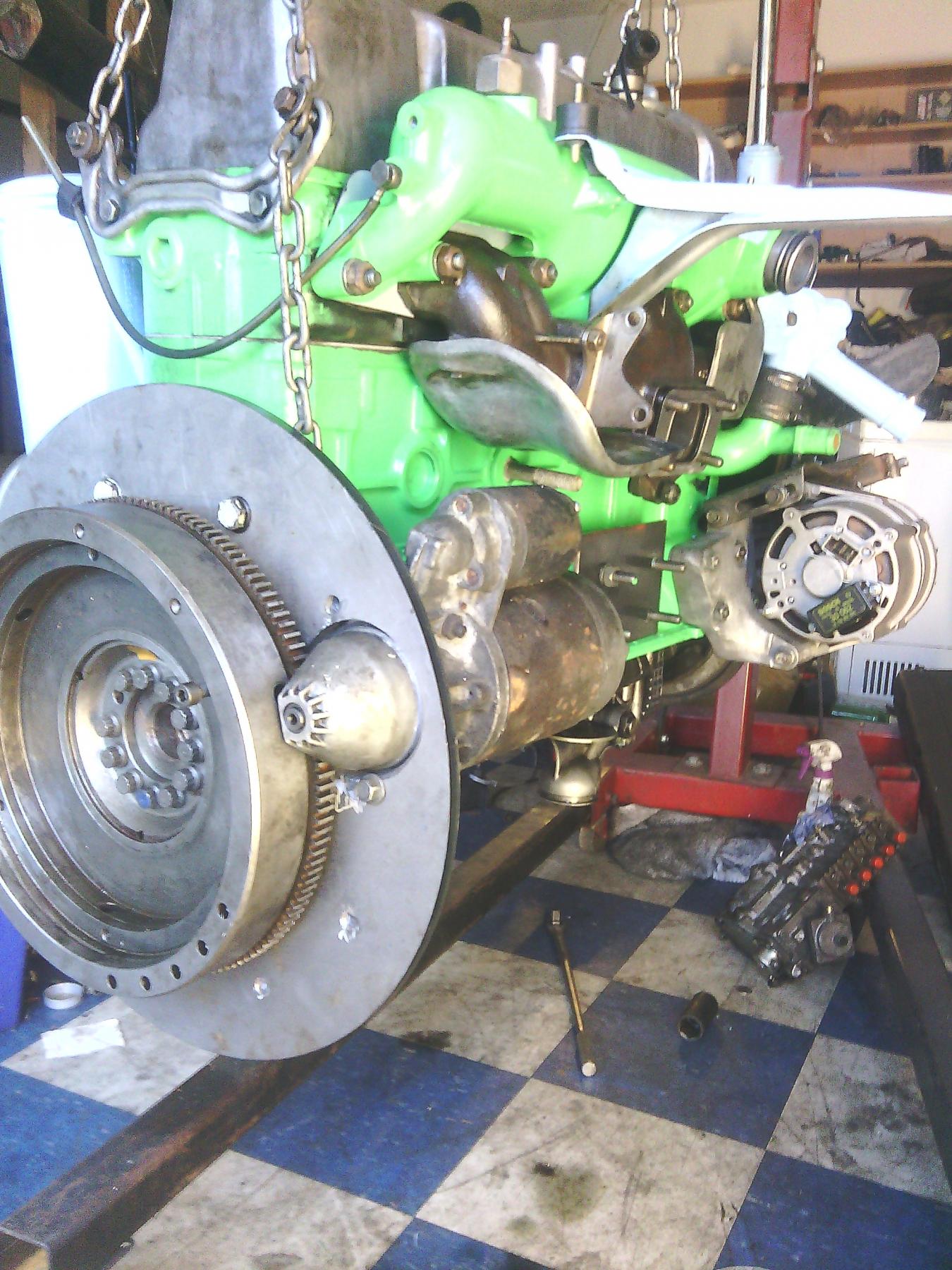
Actually looks like something now.
Here is my Photobucket album for adapter prep. There tells a story of all materials and ideas i went through and things I had to look at to make this part work.
I am in the process of organizing the photos in there as you read this so if there is something in there that is out of order just disregard.
Last edited by raeuspius; Sep 26, 2014 at 01:04 PM. Reason: As I think of something I may have missed, I add it.

Thread
Thread Starter
Forum
Replies
Last Post