
Cruise control questions...


Pro Wrench
Joined: Sep 2011
Posts: 1,526
Likes: 18
From: Oregon
I'm having this exact same problem. Pump, vacuum lines, brake switch, wheel buttons, all tested good. CC switch turns amber. If it lights up does that mean the switch is good? Only components left are ECU and wiring, right?

Mudding
Joined: Jul 2011
Posts: 239
Likes: 0
There's also a cruise lockout relay in there too. Another thing would be to check the CC diode. Not sure what the value is supposed to be but something else to check. There is a VSS output to the cruise ECU from the cluster as well.. If its not seeing the value it wants it wont activate the vacuum pump. There's not a whole lot in the system to check.. Cant even blame lucas for this one as the CC system is all Hella parts..
Pro Wrench
Joined: Sep 2011
Posts: 1,526
Likes: 18
From: Oregon
Finally found the CC relay and a simple test with the multimeter says it's good.
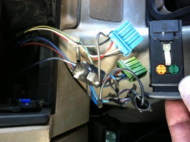
Went to test the button and look at the over-complicated mess I found:
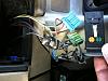
There at most needs to be 6 wires total here but instead we have butt connectors galore and tiny inline mystery circuit boards. As for the switch, 6 pins! What's wrong with a simple 2 pin switch? Ok 3 for the light. None of them seem to have continuity when the switch is pressed either. I tried the fog light switch and came up with the same result. How are we supposed to test these? Finally, what are the green and orange round things on the sides?
Went to test the button and look at the over-complicated mess I found:
There at most needs to be 6 wires total here but instead we have butt connectors galore and tiny inline mystery circuit boards. As for the switch, 6 pins! What's wrong with a simple 2 pin switch? Ok 3 for the light. None of them seem to have continuity when the switch is pressed either. I tried the fog light switch and came up with the same result. How are we supposed to test these? Finally, what are the green and orange round things on the sides?

Super Moderator
Joined: Jan 2011
Posts: 16,322
Likes: 88
From: Savannah Georgia
Circle things are maybe LED lights. That's 4 wires. Dry contact from switch is the other two, maybe. Objects in shrink tubing could be relays, but there are also diodes shown on the wiring diagram. Could be previous owner cluster, or factory "fix" campaign, but does not look like production line wiring harness. When working with LED light may have to reverse meter leads each mesurement. The D in LED is "Diode", and they read in one polarity, not so much in the reverse direction.

Rock Crawling
Joined: Feb 2012
Posts: 267
Likes: 4
From: Southwest CT
The green and orange things are bulbs, one for illumination with dash lights on and the other to indicate cruise is on. Pretty sure my green is burned out, the orange in my truck works and the cruise has no issues.
I think I would start by getting rid of the ghetto wiring and connect it the way it left the factory. From there I would fix the actual problem the hack job went around.
The ETM shows the wiring clearly. I went through all mine a few years ago when I got my Disco, only to find the vac hose cracked at the tee and fell back through the firewall.
You can do what you want, I just don't like electrical fires in the dash.
Last edited by Higgs Boson; Mar 2, 2012 at 09:03 PM.
Pro Wrench
Joined: Sep 2011
Posts: 1,526
Likes: 18
From: Oregon
Thanks I've spent a lot of time staring at the ETM this morning and it's finally making sense.
Can someone test for voltage on the white-blue wire to the vac pump when the CC button is enabled? ETM says voltage is applied by the CC ECU when the button is pressed. I don't get any voltage so I suspect the wiring or ECU is to blame. EDIT: It's also possible to measure the voltage behind the dash at the CC ECU connector on the same wire.
All the other components have tested good so far.
Last edited by EricTyrrell; Mar 3, 2012 at 12:28 PM.
Pro Wrench
Joined: Sep 2011
Posts: 1,526
Likes: 18
From: Oregon
I've tested every single input terminal to the CC ECU and all inputs are exactly as expected. The vacuum pump and solenoid also perform flawlessly. I can suck on the vacuum hose and the throttle modulates with no leak. It must be the ECU. I'll have to wait till tomorrow or Monday to get one from the recycler.

Mudding
Joined: Apr 2011
Posts: 104
Likes: 0
From: Halifax, Nova Scotia
I have the same issue I checked the lines around the pedals and they all hold vaccuum and the switches at the clutch and brake are good as well, I was curious to hear someone say the switches on the wheel can go bad ,maybe a shot of brake clean might help to get them to work.

I have the same issue I checked the lines around the pedals and they all hold vaccuum and the switches at the clutch and brake are good as well, I was curious to hear someone say the switches on the wheel can go bad ,maybe a shot of brake clean might help to get them to work.
The ABS has nothing to do with the cruise control.

