
Attn PaulMC- ACE wiring?
#11
 07-21-2014, 04:35 PM


Im already using the SLS wiring and relay for my front spot lamps, the ACE is the only open relay left but if it isnt beefy enough for the compressor I wont use it. As for the switches, I will use a relay to power the compressor, but the solenoids only draw 5W @ 12v which should come out to .41 amps. I know, more than a regular relay coil, but I dont want to clutter up my wiring with relays if I dont have to. IMO, those contacts look like they might handle the .41amp draw of the solenoids. Im going to bench test that and report back.
Thanks for the replies!
EDIT:
My calculations were close... The solenoids draw 495mA. I grabbed a standard 12v 40A relay and the coil draws 125mA. Grabbing a switch now to test it
Thanks for the replies!
EDIT:
My calculations were close... The solenoids draw 495mA. I grabbed a standard 12v 40A relay and the coil draws 125mA. Grabbing a switch now to test it
OK...
I thought that you wanted to use the ACE wiring on the vehicle, not just the relay.
If you want to use just the ACE relay, it's good for 40A
Have a look at this extract from the wiring diagram -
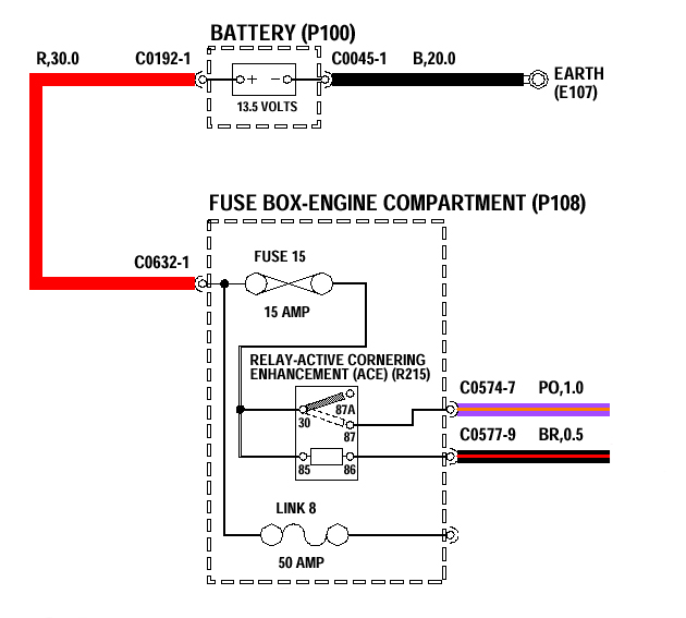
The ACE relay's terminal 30 is fed directly from the main battery feed to the fuse box - so, F15 can be increased from 15A to something a bit heavier.
The ACE relay's earth is controlled by the ACE ECU on C0577-9 - this can be changed for an earth-switching switch.
The ACE relay's output on C0574-7 can have its terminal and cable increased in size.
C0574 is a Sumitomo HD250 series connector - the largest size cable that terminals to fit this connector will accomodate, is - 3.0mm� cable.
I have these 3.0mm� terminals -
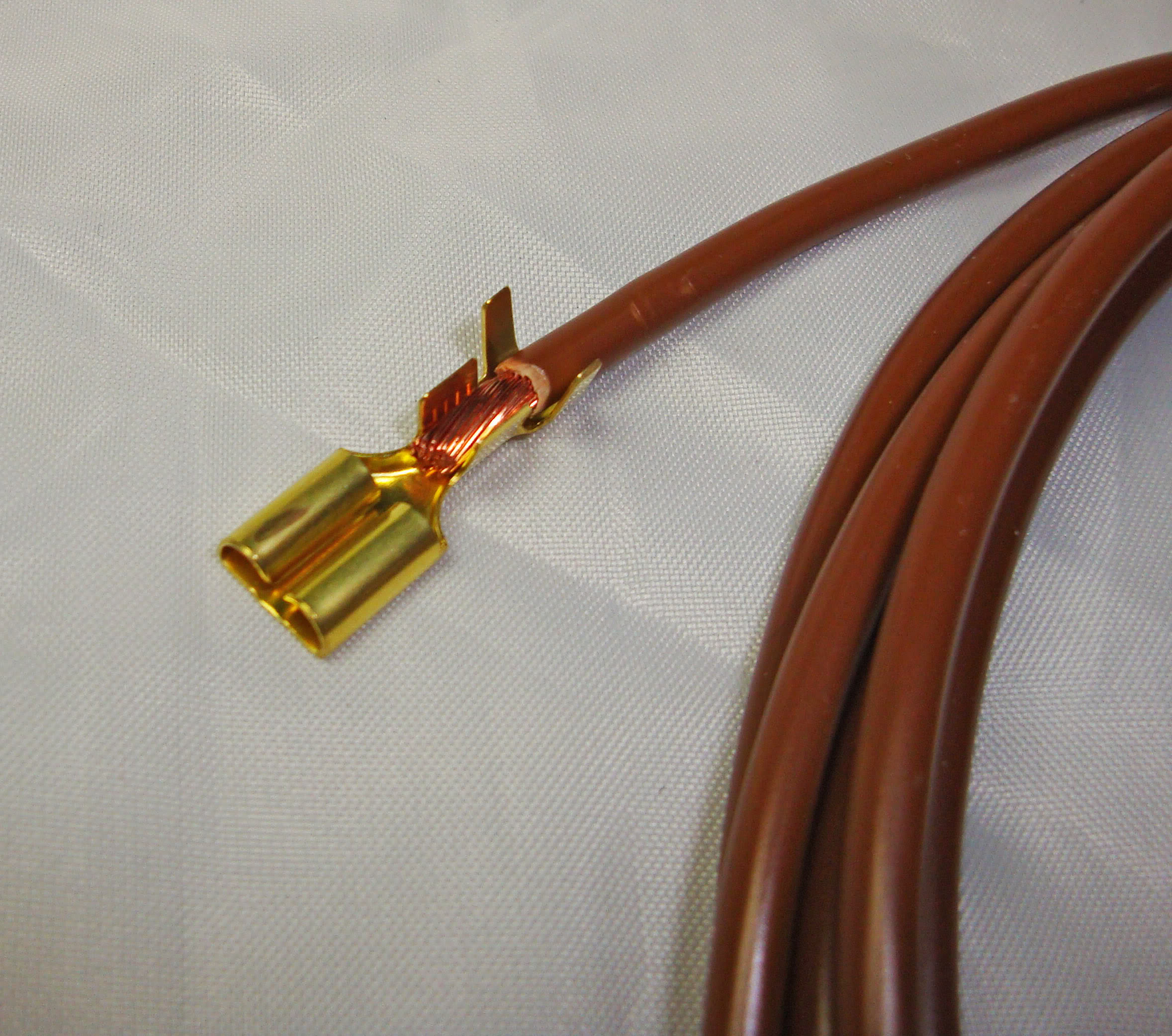
As well as terminals to fit C0577 (Sumitomo HD090 series) -

For the size of currents that you're talking about, I think that you're right, and a relay is unnecessary with the D1 switch.
.
Last edited by PaulMc; 07-21-2014 at 06:27 PM. Reason: To clarify my last sentence.
#12
07-21-2014, 05:50 PM
Excellent info as always, Paul! Good to know I can up the relay fuse if need be.
I tested a D2 hazards switch I had laying around to activate the solenoids... While I have no scientific proof that it will hold up, there was no burning smell or wires getting warm after a 5 minute load test. Like you said, I think they should hold up just fine under a 500mA load.
Thanks again for the help to everyone who chimed in
#13
07-21-2014, 06:46 PM
Excellent info as always, Paul! Good to know I can up the relay fuse if need be.
I tested a D2 hazards switch I had laying around to activate the solenoids... While I have no scientific proof that it will hold up, there was no burning smell or wires getting warm after a 5 minute load test. Like you said, I think they should hold up just fine under a 500mA load.
Thanks again for the help to everyone who chimed in
I tested a D2 hazards switch I had laying around to activate the solenoids... While I have no scientific proof that it will hold up, there was no burning smell or wires getting warm after a 5 minute load test. Like you said, I think they should hold up just fine under a 500mA load.
Thanks again for the help to everyone who chimed in
The D2/Defender switches are bit more sophisticated than the D1 switches (although, they're probably cheaper to make).
This is a D2 switch body split into its two halves.
Circuit board - you can see the marks in the contact grease, where the contacts slide across pins 1 and 4 -
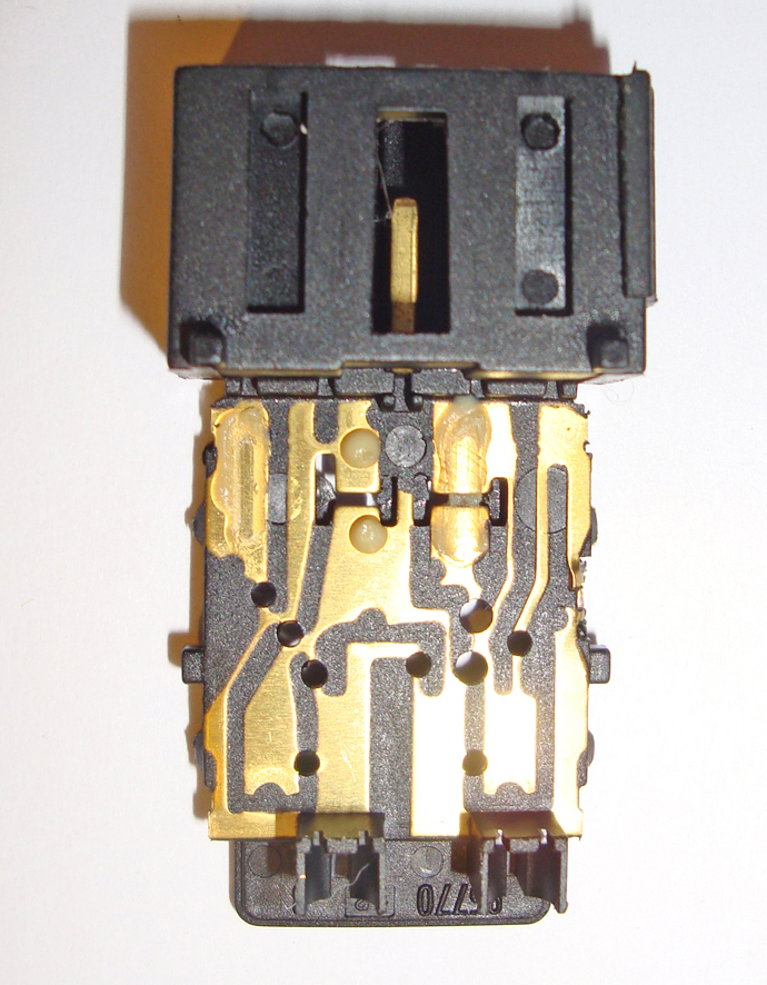
(this switch is a D2 sunroof isolator switch - so, has no LEDs in it)
This is the moving bit, with the contacts -
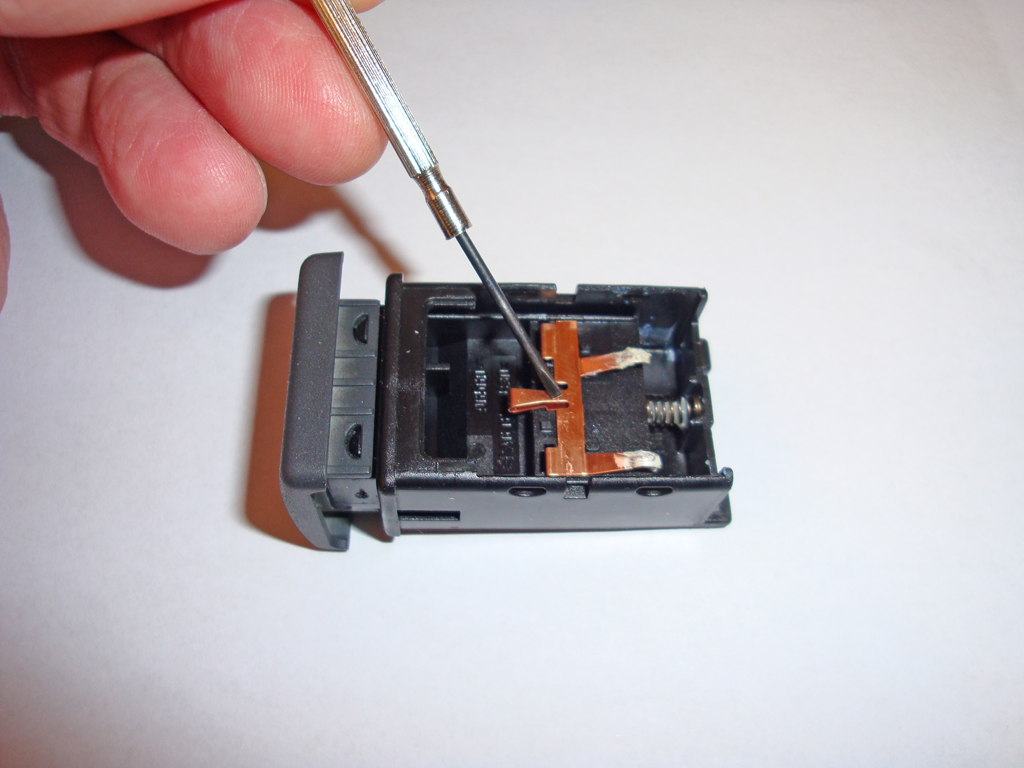
Although they don't look up to much, the heated seat switches of this design, switch the heating elements directly on the D2 and the Defender.
The heated seats circuit is fused at 20A for both front seats, on D2, TD5, and early Tdci Defender.
On 2012 Model Year Tdci Defenders, this has changed to each seat being individually fused at 10A
.
#14
08-11-2014, 04:23 PM
Just to update this thread... I finished the wiring for this project. I did not use the ACE relay for my compressor, but for my light bar instead.
My car did not have ACE from the factory, so the purple/orange and black/red wires were not present. The power feed from the relay, normally purple/orange (Pin 87, or on the Rover Relays, pin 5) is in the brown connector, lower left pin. (red 12AWG wire in this pic)
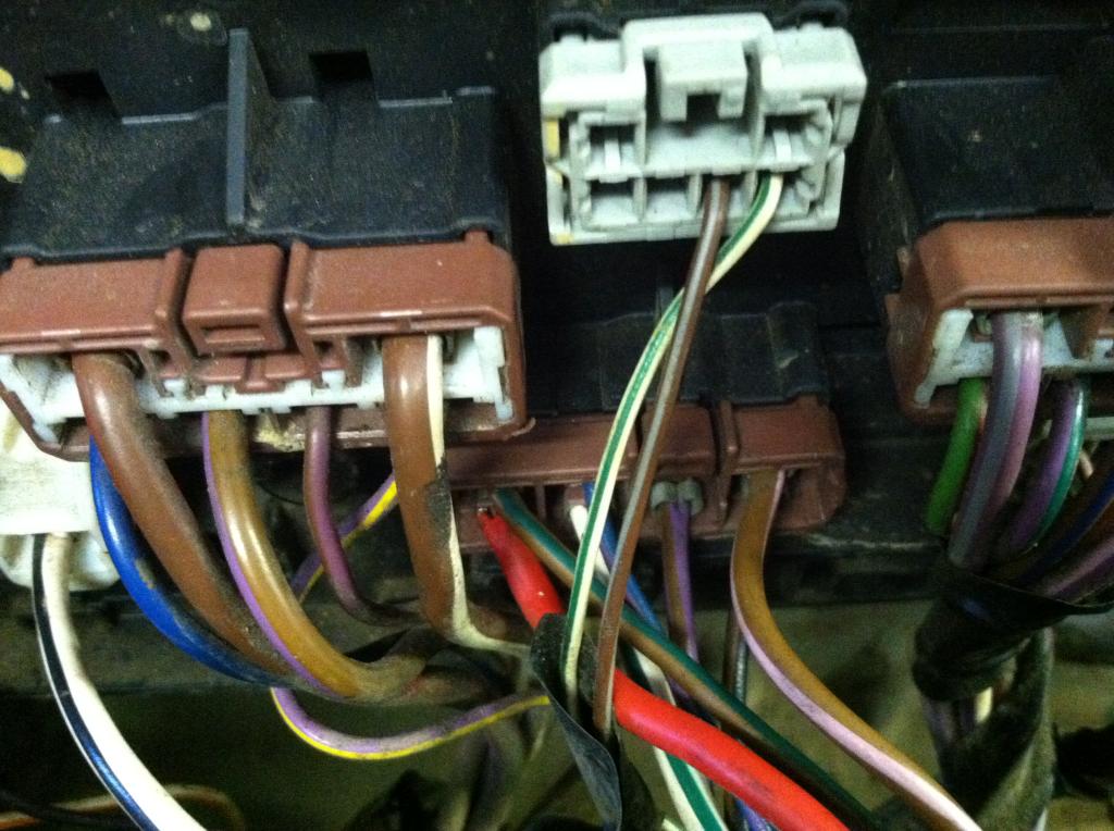
The ground/earth trigger (black/red) is in this gray plug, lower row, 4th pin from the left.
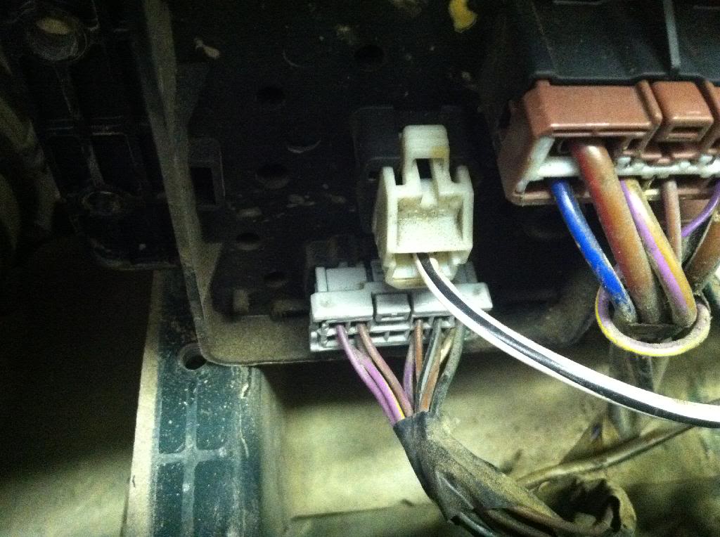
Hope this can help someone else looking to do the same, And thanks to everyone else for your help getting this figured out
Last edited by vette427sbc; 08-11-2014 at 04:25 PM.

Thread
Thread Starter
Forum
Replies
Last Post
EVN137
Discovery II
2
10-07-2009 09:22 AM