When you click on links to various merchants on this site and make a purchase, this can result in this site earning a commission. Affiliate programs and affiliations include, but are not limited to, the eBay Partner Network.
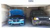
See the attached images. I've got three unused switches/harnesses on the left side of my dash. Green, Black and Blue harnesses. I've got three sets of lights (in-bumper, above bumper and on roof) attached and mostly wired (each set of lights has its own relay and fuse). All I need is to identify the wire that will activate the new relay(s). I'll cut it and splice it to a new wire and connect it to the appropriate terminal in the new relay.
I'm guessing the ground wire is always black and always in space #4. That is the only consistent color/space with each harness. Does anyone know if the hot wire leading to the relay is 1,2 or 5?
Really tricky questions ... 1. Does the purpose of each wire change with each harness? 2. Is every switch (ive got several "clicking" foglight and cruise control switches) wired differently/function differently, or do they all function like a household light-switch?
Seeing as no electrical genius has weighed-in on this yet, I'll just keep sharing my observations see if it triggers someone's D2 mental database.
Just worked every possible combination of power and lights and how they effect these switches with my electrical tester. I discovered that these harnesses (all three) only receive power when the engine is running and the lights are on. The Red Wire in the #2 spot then becomes hot (for all three harnesses). The Black Wire in the #4 spot (for all three harnesses) is always the ground. For the top/blue harness only, with the switch connected (the pulse/no clicking type), the red/yellow wire in the #5 spot becomes hot when the switch is depressed. This is in contrast to the middle harness/switch (black) and the bottom harness/switch (green) which do not get a second hot wire when the switch is activated (both these are the clicking/locking kind).
I cannot exchange switches and harnesses to test further due to each assembly being specifically designed to fit together. As in the switch that fits onto the green harness will not fit onto the black harness ... etc.
Once I figure out how to make that second wire (#5) hot on the black and green harnesses, I'm good to go. Any idea how I do that? Is that mysterious #1 wire the culprit? Or does this have something to do this American D2 not having the wiring completed to make these two switches functional? When I got this D2 both switches seemed to have nothing wired to them.
AHA! Here's an interesting diagram. See my questions, below.
So here are the two remaining question: Why are there two hot wires leading out from this switch (#1 and #5) to one set of lights. AND ... Why didn't my electrical tester detect voltage in both #1 and #5 when the switches were engaged? My apologies for my lack of electrical engineering knowledge. I walked by that building every day at college, but sure as heck never went in!
OK ... now that I stare at that diagram some more and accept that the Control Unit Connector not simply connecting wires direction across from one another ... I'm assuming that I need to bring my hot wire out of my four prong relay into #1 on the harness, and run the outbound wire from #5 back to the relay. Will try that tomorrow night.
I forget what I did when I set my switch up, but I remember I just pinned it out. I could pull it apart and take a couple of pics of what I did. It's pretty messy, I remember that much
Almost have it figured out ... accept that orange diode
Being more mechanic than electrician, this has taken me a while. My plan tonight is to run a hot wire into spot #1 on the harness. I will then run a load wire from spot #5 to the relay. That should do it.
The only thing that confuses me is the orange diode on the first schematic I posted. The diode is on the load wire, and appears to indicate that current cannot flow outward toward the relay/lights.