When you click on links to various merchants on this site and make a purchase, this can result in this site earning a commission. Affiliate programs and affiliations include, but are not limited to, the eBay Partner Network.
Here is the first part of my auxiliary power system I'm installing. When complete the system will comprise of this rear power panel, a dual battery setup to power it, and perhaps some kind of external 12 accessory socket (if you have any bright ideas for that, let me know). I was originally going to install the dual battery system first but that has been a little slow going so I'm starting "backwards" and doing the power panel first, powering it from a removable battery in the mean time. I�m setting up the system so if needed/wanted my removable battery is wired in parallel with the as of yet to be installed aux battery up front (which is why it appears that I have a �breaker to nowhere� in my pictures).
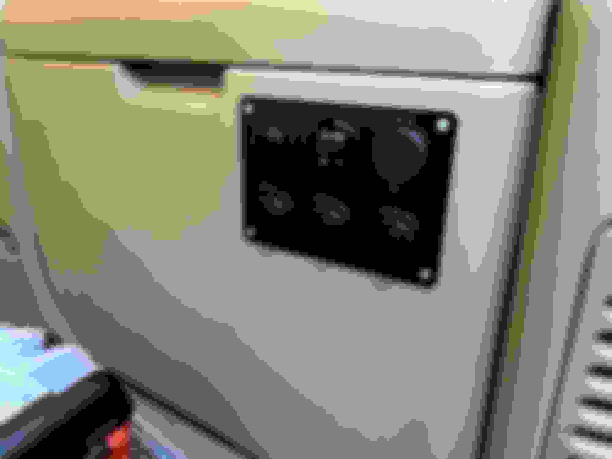
Completed Install
I'm wiring the panel up with 16ga wire (rated for 10 amps) so that the switch on the will turn on the voltmeter and the USB charging ports (through one 10A fuse) and the 3 aux power ports will always be hot (each through their own 10A fuse). This will leave me with 2 extra circuits on the fuse block for future expansion. I'm going to be placing it in the storage cubby on the passenger side as I think this will cause me fewer headaches in running a positive cable from the dual battery setup in the future plus my "camping drawer" sits off to the left in the back.
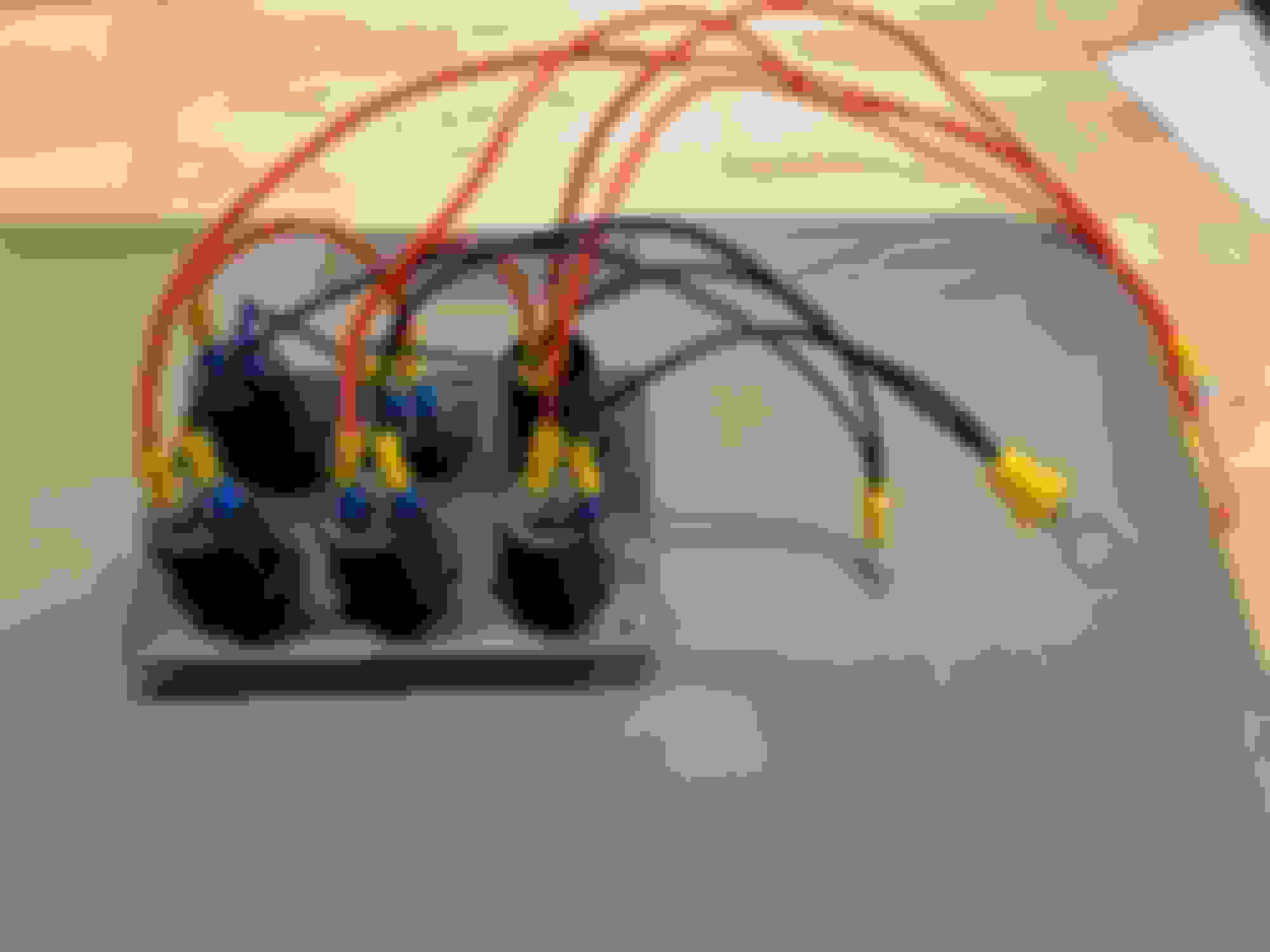
Back side wiring.
For the panel install I removed the side of the cubby (it just pulls off, although it took some force) and traced the outline and holes for the panel. I then had to measure in 7/16th of an inch inside and mark out the cut because the screw holes are placed real close to the ports on this panel. I drilled out the holes with a 5/32nds bit which makes for a close fitment for the 6-32x1/2 countersunk machine screws I'm using to secure it. To actually cut out the panel I used an oscillating multi tool with a wood blade, although I'm sure a jigsaw or Dremel would work equally well. Once the panel was in I refit the ports, although in putting the retaining rings back on they sit on the inside edge of the cubby wall, but they seem to be holding secure so I'm not going to screw with it. To button things up I heat shrinked the positive wires in to a bundle and used an adhesive cable tie mount to secure them. My wires ended up being a little on the long side because I didn't want to measure and fit them while inside the cubby and better too long than too short!
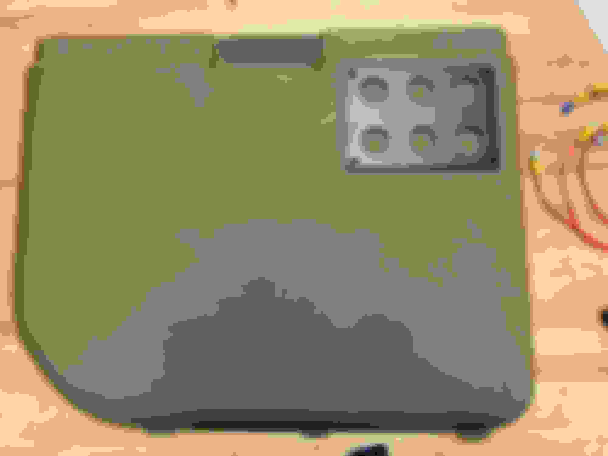
Panel location. Trace, hole layout, and drill. Rough cutout, I used a file to get rid of some of the flashing left over.
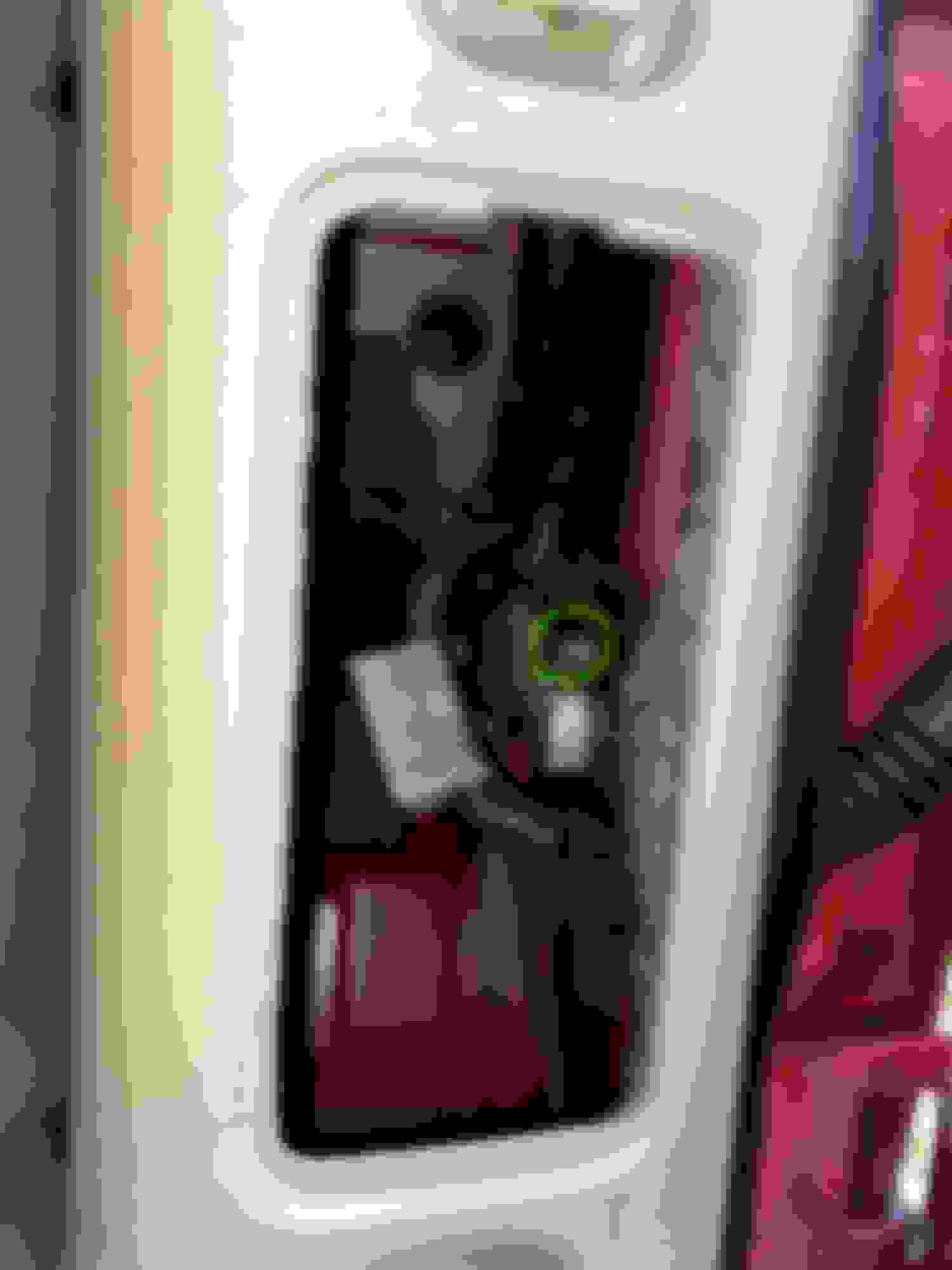
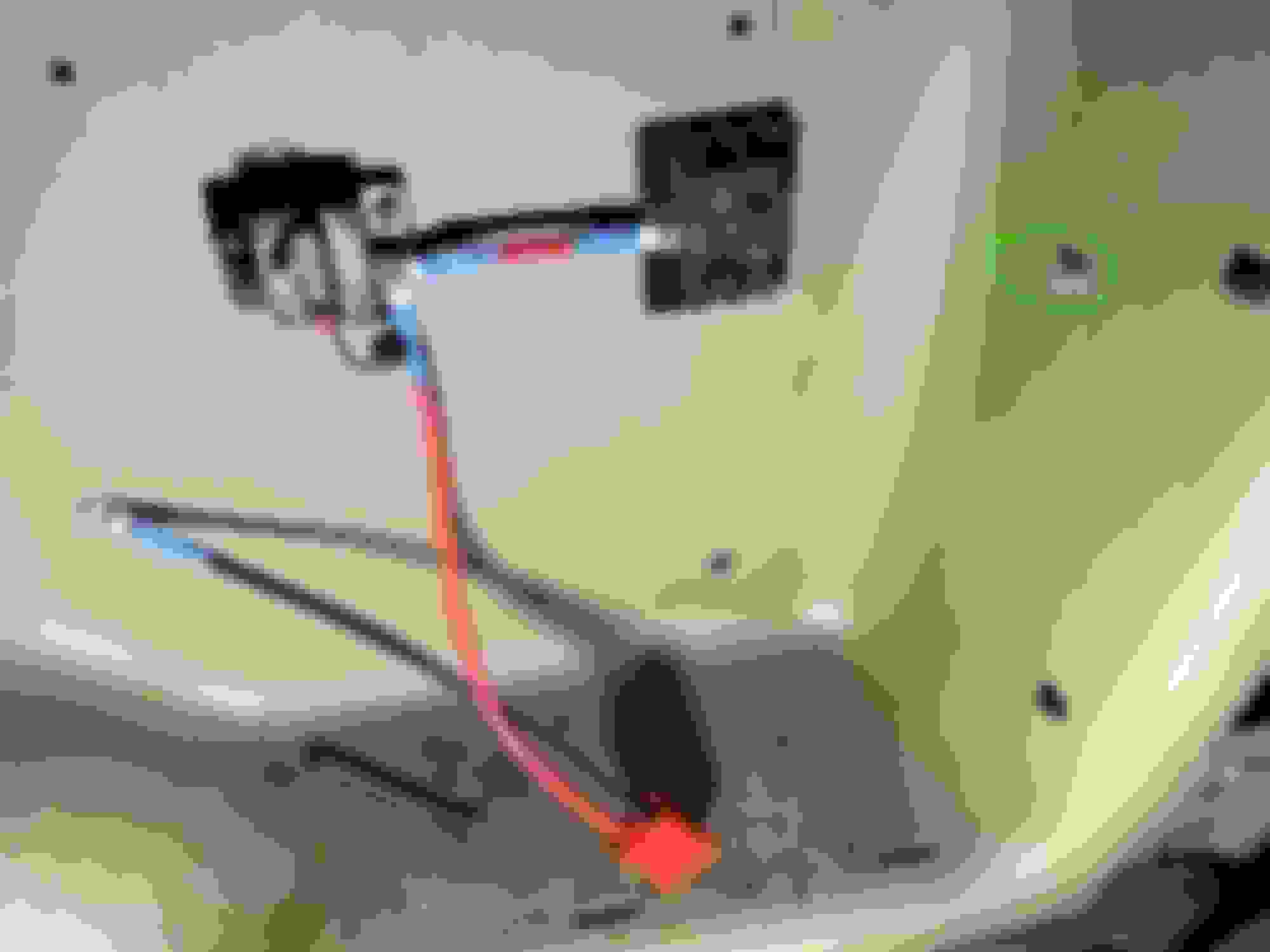
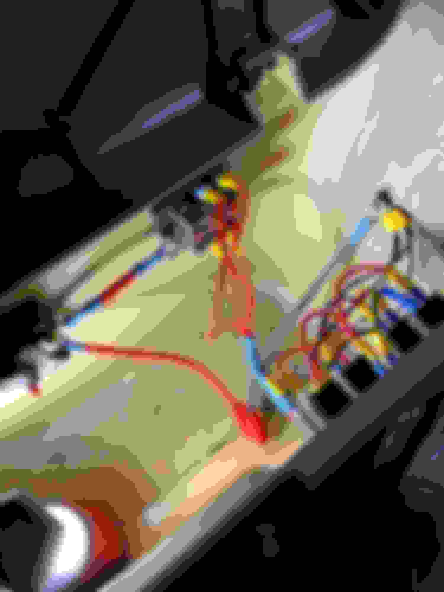
For the fuse block I had to remove the trim casing retaining clips so I could scoot the casing out a few inches, removal of the rear vent then allowed me access to the back to bolt the fuse block and circuit breaker in place. If you plan to do something similar use a drill bit a size to two bigger than needed as the trim casing material is a little gummy and the hole ends up slightly undersized, also watch out for twisting up the sound deadening material as soon as the bit breaks through! For grounding there is a chassis ground bolt (C080 as called out in the RAVE/Electrical Manual) at the back which is super accessible. I ran a 6AWG wire from the grounding bolt to a grounding post I installed in the cubby so that I can tie all of the electrical systems together and make future expansion or repair easier.
Chassis ground just inside of the rear vent circled in green. Rear fuse, fuse/power distribution block, and Anderson power connector for "temporary" power connections. My grounding post is circled in green and connects to the chassis ground. Completed install.
In general I�m pretty satisfied with the setup and am looking forward to getting the dual battery installed with a proper deep cycle battery and an isolator. Obviously you should be comfortable with electrical systems before you attempt something like this but if you have any questions or see something blatantly stupid that I've done (hopefully not) let me know!
Looking nice & Clean - I really can appreciate the sweat equity in D2 fabrication.
question tho; why decision on the top of that storage container?
With your wiring looms all tied in behind it, doesn�t it render all that space in that cubby useless?
Yes, the space in the storage cubby is pretty limited now but I don�t really use that cubby. As for �why there� we use our D2 almost exclusively as a camping rig and I spend a lot of time hanging out near the back with the door open and that�s where I wanted access to the power. Lastly I�m sort of envisioning that space as a bit of an �engineering compartment� and hope to put a small air compressor in there and maybe some sort of Arduino system, but who knows if that will ever see the light of day.
Thank you for sharing this build, I have my mind set to put an additional battery in the same location and your pictures and narrative are very helpful. May I ask how you ran your positive from the primary battery? I'm trying to decide if I should go along the chassis (or if this is even a good idea) or firewall penetration but I'm not really sure where to go from there.
Thank you for sharing this build, I have my mind set to put an additional battery in the same location and your pictures and narrative are very helpful. May I ask how you ran your positive from the primary battery? I'm trying to decide if I should go along the chassis (or if this is even a good idea) or firewall penetration but I'm not really sure where to go from there.
Yeah, so an update an answer to your questions: I installed a dual battery isolator up front (I used the Keyline Chargers kit) and ran a length of the provided 7ga wire through the firewall inside to the back cubby. My wire is just run along the floor so I put it in a plastic split loom for protection. So far there have been no problems. In the back cubby I’ve got a group 65 deep cycle battery which (just barely) fits in the cubby. I never found myself needing more than one 12V car power outlet so I swapped one of these out with an Anderson PowerPole connector and another with a switch to power a small air compressor I installed.. Lastly I ran a power wire up the a-Pilar up to the roof rack where I have an Anderson Pole Connector that I can plug in to from the roof top tent- its nice to be able to have lights, run a fan, charge phones, and even plug in a heated blanket when its gets chilly
To penetrate the firewall there is a large rubber grommet through which a bunch of other wire in goes through in to the passenger foot well. To get the wire to go through I poked a hole through it and tried to enlarge it bit by bit from the engine bay side. I then shined a work light on the little hole and contorted myself in to the passenger footwell with the wire. My memory gets foggy at this point. I either pushed a length of fish tape through the hole taped the wire on and pushed it through or I just pushed the wire through. In either case once it was through I pulled it from the engine bay.
This reminds me of the relay box I built from scratch a few years ago for my last D2. This was a real benefit of not having SAI. It was for lights on the bumper, rack, and reverse. I’m a bit of a nut for wiring and it being clean.
Well done!
This reminds me of the relay box I built from scratch a few years ago for my last D2. This was a real benefit of not having SAI. It was for lights on the bumper, rack, and reverse. I’m a bit of a nut for wiring and it being clean.
Nice! It looks like we did nearly the exact same thing! I like how yours in a protected box, mine is just hanging out in the engine bay. I have two relay on mine- one for my roof lights and the other isn’t being used right now, still looking for something good to wire it up to. I 3D printed out a 3 gang carling switch holder and put that in the slot where the coin tray originally went (the switches are wired to the relay via the CAT5 wires). One switch controls the lights through the relay, another is a low voltage signal to my aftermarket fog lights which change them from white to amber, and the third is (as mentioned) unused. The white bus bars are additionally connected to a few other “always on” devices like my roof power drop and the HAM radio in the cabin.
Dang, nice work guys. I ended up deciding to run my positive down the chassis and I'm going to come up through the passenger tail light. I wasn't too excited about the cable exposed on the floor. Curious though, did you do a write up on your 3D printed Carling switch plate? I had someone print one for me and I can't tell how to keep it in position. Dang thing just slides in and out without resistance.
Dang, nice work guys. I ended up deciding to run my positive down the chassis and I'm going to come up through the passenger tail light. I wasn't too excited about the cable exposed on the floor. Curious though, did you do a write up on your 3D printed Carling switch plate? I had someone print one for me and I can't tell how to keep it in position. Dang thing just slides in and out without resistance.
The one I printed out from Thingiverse had �side springs� which hold it in place. However, I would just get some double sided tape and use that to hold it in if it�s already printed out.
 12-14-2019, 10:31 PM