LR3 Talk about the Land Rover LR3 within.
Sponsored by:
Sponsored by:

C1A13 after new AMK installed...

Thread Tools
 
Search this Thread
 
  #61  
Old 11-30-2016, 08:11 PM
AdrenalinPlease's Avatar
Winching
Thread Starter
Join Date: Jul 2012
Location: Jackson NJ
Posts: 547
Received 4 Likes on 4 Posts
Default

Originally Posted by bbyer
My 3 is a 2005; yours is a 2008?

It looks like the wiring harness changed since 2005. I also see the triangle bracket is gone - bolt holes are there but not the bracket.

I presume you followed the cable back and there are no connectors anywhere easy to see at any rate.

If so, that is probably for the better as those connectors were a trouble spot.

I think I am out of ideas as to where best to look for any cable damage then.

Generally the 2008 three was to my mind, the best built; in 2009 they started to try out proposed 2010 LR4 systems; not all worked well the first try.
mine is a 2007, I am continuing my search for a frayed or broken wire. Tomorrow I will check continuity from connector to connector. Still waiting on the iid tool...
 
The following users liked this post:
bbyer (11-30-2016)
  #62  
Old 12-01-2016, 08:04 AM
AdrenalinPlease's Avatar
Winching
Thread Starter
Join Date: Jul 2012
Location: Jackson NJ
Posts: 547
Received 4 Likes on 4 Posts
Default

Is there a wiring schematic available for this thing?
 
  #63  
Old 12-01-2016, 08:24 AM
bbyer's Avatar
Pro Wrench
Join Date: Sep 2008
Location: Edmonton Alberta Canada
Posts: 1,667
Received 145 Likes on 127 Posts
Default 2 sheet pdf that you can print off

You can download and print off the two wiring diagram sheets per the link below.

DISCO3.CO.UK Photo Gallery - LR3 Air Suspension fuse 35P ECU Manual Shut Off Switch/Air Suspension ECU Fuse 35P Shut Off Switch
 
The following users liked this post:
AdrenalinPlease (12-01-2016)
  #64  
Old 12-01-2016, 03:51 PM
AdrenalinPlease's Avatar
Winching
Thread Starter
Join Date: Jul 2012
Location: Jackson NJ
Posts: 547
Received 4 Likes on 4 Posts
Default So here's what's happening!!!

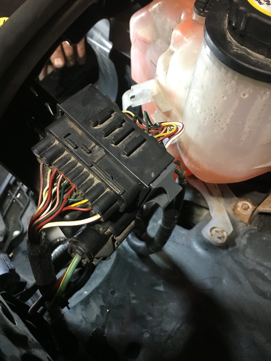
Here is where the interesting connector lives, it is below this one. it's actually one of the ones in your photo that I couldn't find. In MY07 it is behind the LH headlight.
It also housed the exhaust valve wiring, pin #1 and 2, black and white for power pin 1, blue black for ground pin 2.

Here is the diagram I am using from alldata.
we are getting somewhere...
 
  #65  
Old 12-01-2016, 03:55 PM
AdrenalinPlease's Avatar
Winching
Thread Starter
Join Date: Jul 2012
Location: Jackson NJ
Posts: 547
Received 4 Likes on 4 Posts
Default

This is the connector that has the exhaust valve power and ground wires. Pins 1 and 2 respectively. When checking for continuous power or ground, I have neither, unless I pull the F26e fuse, then I have some continuous ground on the power side. No ground on the ground side. Now when I ask the exhaust valve to open the power wire starts to supply ground at a rate of 7.x volts...has to be a short somewhere.
 
  #66  
Old 12-01-2016, 03:57 PM
AdrenalinPlease's Avatar
Winching
Thread Starter
Join Date: Jul 2012
Location: Jackson NJ
Posts: 547
Received 4 Likes on 4 Posts
Default

So for fun I made sure I have continuity at the pump itself and sure enough that harness is fine.
 
  #67  
Old 12-01-2016, 09:36 PM
AdrenalinPlease's Avatar
Winching
Thread Starter
Join Date: Jul 2012
Location: Jackson NJ
Posts: 547
Received 4 Likes on 4 Posts
Default

Forgot to mention, tomorrow we will be looking at the connector at the module itself C2320.
 
  #68  
Old 12-01-2016, 09:43 PM
EastCoast's Avatar
Winching
Join Date: May 2016
Posts: 614
Received 29 Likes on 29 Posts
Default

Did anyone else pick up on the broken green wire in the first pic?
 
The following users liked this post:
bbyer (12-02-2016)
  #69  
Old 12-01-2016, 09:52 PM
houm_wa's Avatar
Camel Trophy
Join Date: Apr 2009
Location: North of Seattle
Posts: 4,161
Received 468 Likes on 419 Posts
Default

Woah!!!
 
  #70  
Old 12-02-2016, 12:13 AM
bbyer's Avatar
Pro Wrench
Join Date: Sep 2008
Location: Edmonton Alberta Canada
Posts: 1,667
Received 145 Likes on 127 Posts
Default the green between the red and yellow conductors

Originally Posted by EastCoast
Did anyone else pick up on the broken green wire in the first pic?
Are you referring to that green wire between the red and yellow conductors - the green does look broken, and no, I looked but did not see it until you mentioned it. Is that connectors C2559/C2560?

That must matter - a broken wire is no minor matter.

I am impressed with your ability to see what none of us did.


Quick Reply: C1A13 after new AMK installed...


All times are GMT -5. The time now is 05:27 PM.