When you click on links to various merchants on this site and make a purchase, this can result in this site earning a commission. Affiliate programs and affiliations include, but are not limited to, the eBay Partner Network.
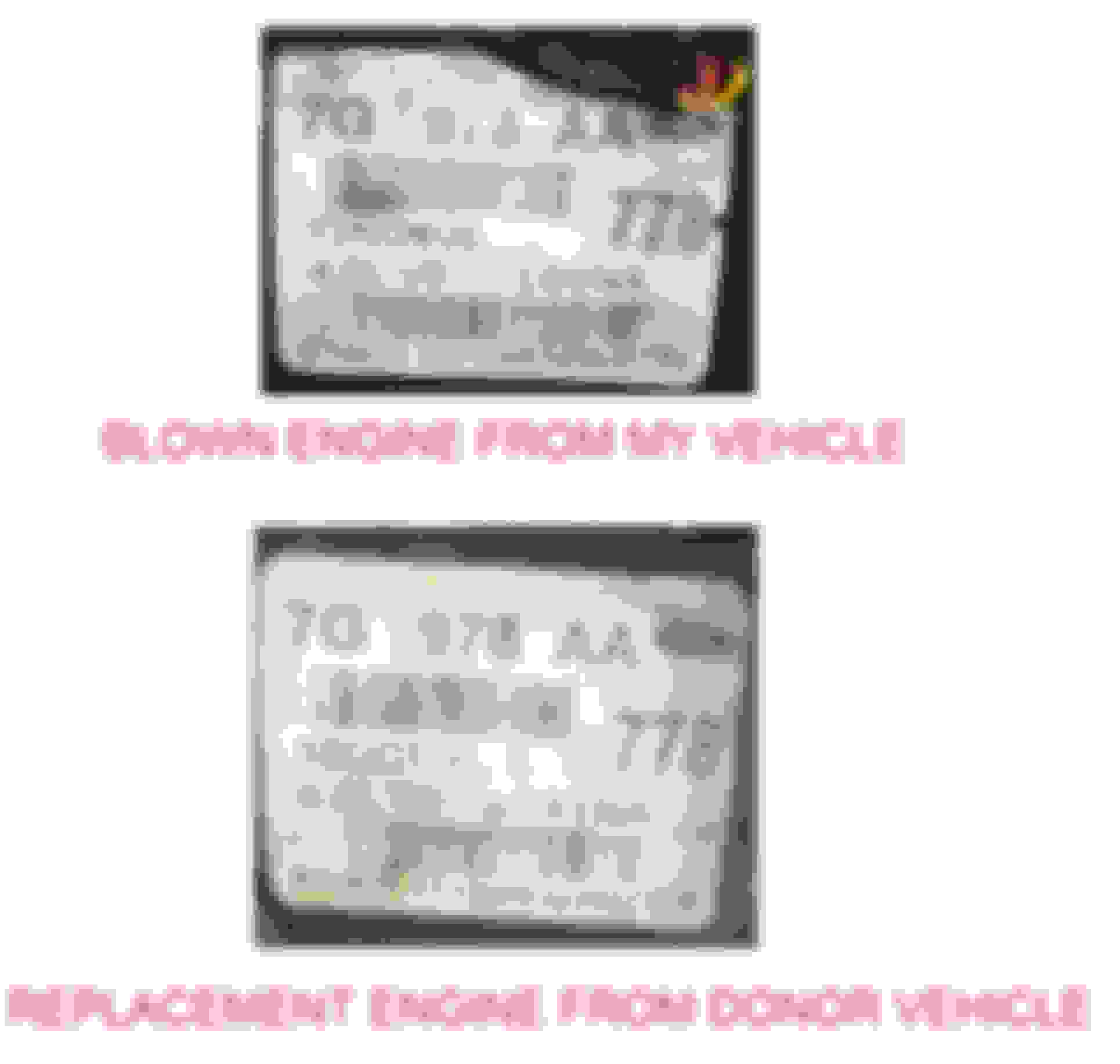
I recently bought my first Land Rover - a 2007 LR3 4.0L V6 VIN: SALAE24487A437*** with a blown engine. With a lot of luck I was able to procure a used engine that is not out of a Ford, or so it appears. Just got the engine out today and I have attached photos of the old and new engine stickers which seem to be identical and only a month apart in production. The only thing to note is some different casting and the lack of an oil temp sensor on the bottom end. To the seasoned LR3 techs out there... Is this a stock LR3 engine or some kind of Ford E1W21 Frankensteind monstrosity? Why is it missing this sensor if not the latter?
---------------
Hi DerChamp, just PM'd you but looks like from the photos you have a SOHC Ford V6, you can tell by the engine mount drilled holes in the block casting, and the lack of a threaded hole for the oil temp sensor. It is a pretty straightforward swap as these engines are exactly the same internally except for the block casting engine mount holes. Read over the thread https://landroverforums.com/forum/lr...ild-kit-93456/
Detailed Provisional Ford Cologne V6 Engine Replacement
Ford 2008 Ranger Cologne 4.0L V6 to Land Rover 2007 LR3 Cologne 4.0L V6
Read these instructions end to end until you understand what you are about to do, this project is not for the uncommitted! This is a potentially dangerous undertaking, I may have forgotten or missed a few things, this document is for informational purposes only!
Before starting this project, ensure you have a helper, the correct tools, supplies and shop facilities functionally similar to what we had which was; at least 10 containers/bags/sacks to record/save the various nuts and bolts you’ll be removing, a white or yellow paint pen (for marking), a few trouble lights, lots of shop rags/towels, channel lock pliers for water hoses, small screwdrivers for unlatching electrical connectors, metric ratcheting box wrenches, six sided wrenches, six sided sockets both deep and regular in �, � and 3/8 inch drive, with extensions and universal joints as required. We also used � inch drive impact tools (air and electric), � inch drive electric impact tools and a 3/8 inch drive air ratchet. We used a drive on 9 ton vehicle hoist, a 1500 pound engine stand (you may need 2 engine stands) and a 2 ton hydraulic engine hoist with a homemade cylinder head mounted engine lifting plate.
1. Drive on to or align with your vehicle hoist, point front wheels straight ahead and remove the ignition key.
2. Wait at least an hour to let the engine cool down, unless you enjoy being burned by hot fluids and exhaust components.
3. After removing ignition key from the ignition wait approximately 10 minutes (allows filter capacitors to discharge) and then open hood, remove negative cable from battery, then positive cable, followed by battery removal.
4. With assistance from a helper remove the hood. It is made of aluminum and is light, but unwieldy, that’s why you need a helper. You can leave the hood on, but it blocks light and makes the whole process a bit tougher, it’s your choice.
5. Remove the top engine cover, exposing wiring, overhead valve covers and the intake manifold
6. Remove the engine skid plate(s) and transmission skid plate and the transmission skid plate mounting bracket.
7. Drain the engine coolant by disconnecting the lower radiator hose at the “T” connection, there is no engine coolant drain valve, so be very careful.
8. Remove the transmission cooling lines at the radiator using a suitable container to catch fluid as it exits, and tie them up so they don’t leak on your shop floor. Note how much transmission fluid drains out, you will need to add this amount later.
9. Drain engine oil.
10. Disconnect exhaust pipes from exhaust manifolds.
11. Disconnect wiring pigtail WPT-1231 (Ford part# 3U2Z-14S411-DVAB) from oil temperature sensor Ford part # 4L3A-12A648-AB located on the driver’s side of the aluminum engine girdle
12. Disconnect oxygen sensor below starter motor (driver’s side) and remove it, it blocks easy access to the starter motor bolts
13. Remove the serpentine belt by using a 3/8 inch drive breaker bar in the tensioner slot to loosen the belt
14. Remove the upper fan shroud, followed by disconnecting the electrical fan connector, then using a 36mm wrench on the fan nut, with a strap wrench holding the pulley remove the fan and clutch assembly (lefty loosey, righty tighty)
15. Remove the lower fan shroud assembly, this should give you much more room to work
16. Remove alternator bracket and alternator, remove bolts holding power steering pump and air conditioning compressor on front of engine and place them out of the way, they will not be removed from the engine bay
17. Remove the electrical connections to the starter motor. Land Rover instructed us to “remove exhaust system” as part of this process, but that was unnecessarily complex. We started by removing both engine exhaust manifolds, then removing the lower starter motor electrical ground (not sure this is necessary) and bottom starter bolt. The driver’s side exhaust manifold has the EGR pipe attached, we undid the top EGR nut and left the manifold connection on, it was very corroded and we didn’t want to break it. We later had to undo it because we encountered difficulties reinstalling the driver’s side exhaust manifold. Then remove the positive cable and solenoid control lead, followed by the upper starter bolt. The starter motor is now easily removed.
18. Next, disconnect all the wiring on top of the intake manifold and around the engine, fuel injectors, alternator, sensors, etc.
19. Remove the bolts holding the intake manifold to the top of the engine, they are TORX type (the last one at the rear driver’s side cannot easily be seen, you must feel your way around it), then lift off the intake manifold and tie up the wiring toward the windshield to get it out of the way
20. Remove the wiring harness holder at the rear of the engine, the bolts are very hard to get to, while you are doing that remember to remove the electrical ground straps at the rear bottom of each side of the engine heads/block
21. Remove any coolant hoses (like water pump) or other connections which are still on the engine
22. Undo the large single nuts on the motor mount to frame adapters (one nut per mount) and undo the transmission mount bracket but leave the transmission where it is
23. Looking through the starter motor mounting hole, use a 19mm socket to rotate the engine (clockwise from the front) until you can see one of the 4 torque converter (TC) to flexplate mounting bolts. Remove that bolt and rotate the engine crankshaft to the next bolt, removing all the remaining TC to flex plate bolts
24. Remove the bottom 4 bolts holding the transmission to the rear of the engine, and this is the time to think about how you will support the transmission so that the torque converter does not fall off when removing the engine. You can figure out some straps or use blocks, but you do have to support it somehow. Our drive on lift had a separate trolley and hydraulic support yoke system specifically designed to support the transmission, so we were darned lucky
25. Carefully check the engine to ensure there are no electrical connections left on the engine, there is an engine electrical ground cable at the front passenger side and a harness support at the front of the oil pan, plus the transmission cooler lines are held in at the front driver’s side bottom of the engine. Also don’t forget the camshaft position sensor on the valve cover top rear on the driver’s side
26. Remove the crankshaft position sensor on the transmission housing at the 11 o’clock position when facing the rear of the engine, or at the 1 o’clock position when you are in the engine compartment and actually removing it
27. Carefully undo the bolt holding the steering yoke to the lower (by the driver’s side motor mount) part of the steering assembly and move the upper shaft aside (towards the driver’s side fender)
28. Remove the 4 top bolts holding the transmission to the rear of the engine
29. Carefully inspect that there is nothing attached to the engine which would impede its removal and that the transmission is properly supported
30. Use a fuel line disconnect tool to remove the fuel line to fuel injector rail connector, but be careful, fuel will spill all over the engine. Remove injector rail
31. Securely attach the engine pulling system/device of your choice to the engine and attach it to your lifting device
32. Before lifting engine, be aware that it can tilt forward when released from the transmission and could possibly hit the air conditioning condenser and engine cooling radiator, causing you to curse and swear a lot
33. Use a breaker bar to break the torque on the left and right motor mount to engine block bolts (4 bolts per side)
34. Slowly lift the engine until it is just very slightly off the motor mount pads on the frame
35. Remove the four (4) driver’s side engine to motor mount bolts
36. Remove the passenger side (4) engine to motor mount bolts
37. Pull forward to break free of the transmission alignment pins and carefully raise the engine assembly to clear the vehicle engine bay
38. Mount the engine on a suitable engine stand so that you can compare everything in preparation for transferring from the LR3 4.0L SOHC to the Ranger 4.0L SOHC
39. Engine Differences and information follows
40. Bypass hose (top housing to water pump) is Ford KM3269 (97-JM-8548-AG)
41. Spark Plugs are NGK TR55 1GP
42. Fuel Injectors are Bosch 0280-158-055 (same as Ford Ranger)
43. Engine Flex plate to crankshaft spacer measures out to be the same part exactly
What you need to transfer or fabricate for the Ford 4.0L SOHC V6 Engine
The internals of these engines are exactly the same and so are the cylinder heads, but the engine block for the Land Rover has several differences in terms of holes drilled and tapped and the mounting position for the 4-5-6 cylinder bank knock sensor, so you’ll have to transfer and/or fabricate the following:
1. The knock sensors, one in the valley between the heads, the other is on the 4-5-6 cylinder bank
2. The engine girdle on the Ford must be drilled out and tapped to accept the oil temperature sensor (located in the engine girdle) or if you like a challenge you can remove both girdles and install the LR3 one on the Ranger engine. This is a lot of work and has disastrous consequences if not done absolutely perfectly. Google FordTechMakuloco’s “Ford Explorer Ranger 4.0L SOHC Startup Rattle Fix” for the complete complex process of ensuring your engine cam timing is right and the girdle is aligned to the rear of the engine block EXACTLY flush.
3. The oil filter mounting bracket from the Ranger interferes with the passenger side motor mount, so either use the LR3 one or grind off the interfering part of the Ranger’s
4. The flex plate and spacer, including the engine to transmission spacer plate shield
5. You must install the flex plate by first ensuring the engine is set to #1 cylinder at TDC on compression stroke, if this is not done correctly the engine will not run and you will be removing the engine to fix it again!
6. Verify by removing #1 spark plug and turning engine until #1 piston is at top of its stroke, then examine the ends of the camshafts. Each camshaft MUST have the slots below centre line and parallel to the valve cover mating surface of the cylinder head. If not, then engine is NOT on compression stroke, rotate engine (19mm socket on harmonic balancer) clockwise from front until both camshaft’s slots are below cam centre line and parallel with cylinder head valve cover mating surfaces.
7. Now attach flex plate to crankshaft so that registration hole in flex plate is at the 3 o’clock position, which is pointing to the alignment pin in the engine block at the 3 o’clock position viewed from the rear of the engine.
8. The Land Rover 4.0L V6 SOHC engine block has different motor mount holes drilled/tapped in the block casting than the Ford 4.0L V6 SOHC, so the following steps are required
9. Left or driver’s (North America) side motor mount will need to be fabricated from a Ford Ranger 3 hole motor mount and a hole opened up so you can attach the knock sensor to the engine block, this hole is approximately halfway between the front lower mount hole and the middle upper mount hole on the fabricated engine mounting bracket
10. Passenger side motor mount will have to be modified slightly (grind out top right corner and mill a spacer washer to fit behind) to be used with the Ford SOHC engine
11. We used the Land Rover oil pan and dipstick tube and dipstick assembly, they seemed to be a bit higher capacity
Installing the New Engine
1. We did not attach exhaust manifolds, motor mounts, the driver’s side OHV cover or the oil filter, the engine was much easier to maneuver and install without them
2. Attach your mounting device to the engine so that you can easily lift and control the engine’s position in the engine bay and proceed to get the engine into position lining up the transmission and rear of engine with the alignment dowels in place. It is not a good idea to try to install the engine without the alignment dowels. Do not use excessive force, the engine and transmission should connect fairly easily, so if they don’t there is something wrong.
3. Install all 8 transmission to engine bolts, they are all the same length. We had a problem with the bottom bolt at the alignment dowel on the starter motor side, it was bottoming out with about 1/8” still to go, the Ford block at that point was about 3/16” thinner than the LR3 block, so we ground off the bolt by about 3/16” and it then went in fine. You could also tap out the threads so they go completely through, but we did not have a 10 X 1.5 tap handy
4. At this point the engine is still being supported by the lift, so it is time to attach the motor mounts and let the engine down in its final position, attaching the frame to motor mount nuts
5. Remove the lift from the immediate work area and remove the rubber inspection plug at the front bottom of the transmission housing so that you can check that the torque converter turns easily
6. Get a 19mm deep socket and ratchet for the harmonic balancer, you’ll be using this to turn the engine in a clockwise direction (facing it from the front) to access the bolt holes while attaching the flex plate to the torque converter bolts (4)
7. Attach all the bolts (4) and torque to 35 ft lb, then replace the rubber inspection plug
8. Attach the starter motor and its associated wiring, not forgetting the engine oil temperature (EOT) sensor connector, which is in the same area of the wiring harness
9. Attach electrical ground connections to rear of engine and don’t forget that PCV valve connector at the rear of the driver’s side OHV cover.
10. Attach oil pressure sensor (driver’s side front) connector
11. Reconnect steering box U-joint
12. Connect lower engine knock sensor and upper engine knock sensors to their respective connectors
13. Ensure electrical cables at engine front and rear are able to reach their respective end positions, and do not install the RF suppression capacitor to the block, it should be on the intake manifold (we made that mistake)
14. Install fuel rails and do not forget to attach the fuel line connector
15. Install intake manifold, the last torx bolt on the driver’s side closest to the firewall is a real hard to get at beast, a mirror or a fibre optic television camera can be your friend
16. Install ignition coils and associated wiring
17. Install alternator, serpentine idler pulley, serpentine tensioner, power steering pump and A/C compressor assembly to front of engine
18. Place serpentine belt (Continental Serpentine Belt 4060820) in position for installation but do not install yet, you need to install the engine fan assembly first
19. Install lower engine fan shroud, engine fan viscous clutch assembly (righty tighty 36mm)
20. Install serpentine belt, Google 2008 Ford Ranger 4.0L V6 (with air conditioning) for the routing diagram
21. Install radiator hoses, heater hoses, and do not forget the transmission cooler upper and lower hoses
22. Add the same amount of transmission fluid that you drained at the beginning into the upper transmission cooler hose before reconnecting it. We used Ford Ford Mercon SP (low viscosity synthetic)
23. Install air box/filter assembly and intake pipe, plus all associated wiring (mass air, etc.)
24. Check that main engine electrical ground cable is attached to engine, passenger side front lower
25. Check engine oil level
26. Add 50/50 glycol solution to engine with heater controls in the full heat position, look down between radiator and lower shroud assembly to check for radiator core leaks and check under vehicle for same
27. Install upper radiator shroud assembly
28. Install battery
29. Check engine oil level
Last edited by enb54; 04-18-2020 at 01:35 PM.
Reason: Step 11 Add LR oil pan and dipstick assembly
I recently bought my first Land Rover - a 2007 LR3 4.0L V6 VIN: SALAE24487A437*** with a blown engine. With a lot of luck I was able to procure a used engine that is not out of a Ford, or so it appears. Just got the engine out today and I have attached photos of the old and new engine stickers which seem to be identical and only a month apart in production. The only thing to note is some different casting and the lack of an oil temp sensor on the bottom end. To the seasoned LR3 techs out there... Is this a stock LR3 engine or some kind of Ford E1W21 Frankensteind monstrosity? Why is it missing this sensor if not the latter?
---------------
Top is the blown engine WITH sensor installed:
Was the replacement engine sold to you as a Land Rover 4.0L? What does the intake manifold look like? Looks like the valve cover was swapped off a Land Rover engine and installed on a run of the mill Ford 4.0L
As 5280LR3 points out, looks like you got sold a LR3 engine when it's really a Ford Ranger (or similar) Cologne V6. All's not bad, you can easily sub this engine for the real one, I've got 15,000 Km on mine and no problems! Just read through these forums and if you need some assistance, I'm sure we'll all pitch in. We all have our own opinions about some of the things to do, but we do agree that the engines are basically the same...
Good Luck!
From the photos I'd venture that the 2nd knock sensor has been relocated and that the oil temperature sensor has been bypassed (somehow), but the intake manifold and ignition coils are there so that's a good thing! The last important and expensive part is the toothed flex plate bolted to the crankshaft, but because of the uncertainties associated with this engine, I'd be inclined to take it apart and pay real close attention to the front and rear timing chains and cassettes. Read the Ford Explorer 4.0 SOHC forum thread on these engines, they are very reliable and robust if properly maintained, the key word being "properly"...
Where did your replacement engine come from? A coastal area maybe? That's some pretty heavy corrosion on the aluminum parts and the bare steel sections. That was either in a flood or has been sitting out in the elements for some time. As enb54 said, you should pull this apart and do some inspection. Drain the oil out and see how milky it is. If there is no oil in it you can swab inside the drain plug to see what gunk is inside the pan. Better yet, pull the oil pan. Then you can get a picture of what's going on with any interior corrosion and look for plastic bits from the cam chain guides.
MileLR3 agreed! I think that engine looks like it came from a place where they salt the roads to beat Hell, like Toronto or Detroit, or possibly the highway between Quebec City and Rimouski (QC), where I once used 4 litres of windshield washer fluid back in February of 2001 just on that trip. Out here we use very little salt on the roads, but we do have potholes galore and I heard they'll all go away once we convert to electric cars...


 04-18-2020 | 01:13 AM


 ... Here are more photos...


