When you click on links to various merchants on this site and make a purchase, this can result in this site earning a commission. Affiliate programs and affiliations include, but are not limited to, the eBay Partner Network.
The Land Rover winch was a dealer installed option (I think the actual G4 Challenge cars were factory). This relay was used to power on the winch controller ONLY when the ignition was on. That way you could not run down the battery using the winch with the engine off. (also maybe to make sure you had enough power to run the winch).
IF you are adding a HF winch, this would only serve to isolate the winch when the power is off.
Anyway in case you are interested in how it is wired, here is the installation manual.
I had a read of the instructions, very IKEA of them really, and on page 7 I see my relay installed and the wiring needed. So apparently the factory did see a need for a relay for the winch.
I also have a relay and wiring for driving lights, the relay is by the battery box, the wires are behind the grill. The switch right now is in the glovebox as I removed it to accomodate a USB port for phone charging, among my next projects will be moving the USB somewhere else to put the switch back in and reinstalling the switch. I have some Hella big lights that might get the nod, and have the relay and wiring already installed.
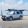
A couple of easter eggs. Next step, remove the bumper to see what might be hiding under there.
. Next step, remove the bumper to see what might be hiding under there.
Look at the bolts holding the bumper supports on to the frame. The instructions require you to drill out the welded on nuts on the frame and install bigger bolts with nuts in their place.
Your Rover certainly has some unique features. keep digging, it sounds interesting.
Thank yu for posting the instructions for sure-and yes, unique features.
Most of the youtube university videos show the winch mount being directly screwed into those threaded holes, drilling them out and upgrading sounds like an excellent idea! I do have a HF winch and bracket, bought it for the 6G Bronco I had for a couple years and never got around to putting it on that rig. The hidden mount for that was $300 and mixed reviews on the actual quality, one of the local Bronco guys bent the snot out of his when he actually had the temerity to use it.
And then I have a brush guard from a RRC I'm going to rehab and adapt to the LR3, so I'll need the bumper off for that.
edit-when I run a scan on the rescue rover I get a "relay coil open" as a persistant fault. Not sure if it's that relay or the other one I found. Might be time to find out
That way you could not run down the battery using the winch with the engine off.
That is rather brave. Imagine being a bog hole with the chance of being able to suck in water into the engine and needing to winch out, but one can not. With all that I have see, I could never have that. I would rather drain a battery than kill an engine.
The suspension light came on in my 2008 with codes C1131-92 "Air supply - component failure - performance or incorrect operation" and C1A20-64 "Pressure increases too slowly when filling reservoir - Algorithm based failure - signal plausibility failure". I checked it out and could feel air pressure coming out the exhaust port while the compressor was running. Pulled the compressor unit and found the exhaust valve was stuck. Cleaned it all up, greased o-rings with silicone grease, refreshed the desiccant, and this AMK with 2012 date code is back up and running. This youtube is a good reference:
New OEM AMK compressor installed ~1 year ago (plus reservoir tank, center valve block, and front valve block replaced at the same time).
Replaced fuses FL10, F26, F3, F35
Replaced relay (R7)
Battery disconnect (15 min) � no change.
Cleared code multiple times with scan tool � code comes back instantly, compressor never even attempts to start.
Scan tool shows:
Compressor relay = OFF (never commanded ON).
Compressor voltage = 0 V.
Pressure sensor Vref = 4.9 V (so ECU is powering it).
Gallery pressure stuck at ~12.8 psi.
Rocker panel under passenger door had water intrusion (sunroof tubes duh); loom dried but still suspicious.
Current suspicion:
ECU is not seeing a valid signal from the reservoir pressure sensor (inside reservoir valve block).
Either the sensor itself is bad OR the signal wire is open/corroded in the passenger rocker loom.
Next step I�m considering:
Running a continuity test from the pressure sensor signal wire at the reservoir valve block back to the suspension ECU behind the glove box (long jumper wire).
Question for the community:
Does this sound like the right next diagnostic step? Has anyone else confirmed a rocker-loom wire failure (open or corroded) as the root cause of a C1131-92 with a non-running compressor?
New spark plugs this weekend along with some other stuff. Just posting about the plugs because the ones I pulled had 100k on them and were, at the time, the fairly new to the market NGK RUTHENIUM HX. These are suppose to go well past 100k in some applications with 120k miles typical. And I tend to agree that would have been possible. I only swapped them because I had new NGK Platinums on hand to put in. But they looked great and the gaps were all okay. Only slightly more than 1mm and probably well within spec range. I really think I could have got 120k or even 150k miles out of them. Also keep in mind these had a hard life since I had a lean issue for a couple years - valve cover gaskets.
After a year of fighting it, I replaced the battery.
Is there a battery reset for the LR3? I looked through the various Gap tool menus and couldn't find anything like that.